Content .. 1978 1979 1980 1981 ..
Chrysler 300/300 Touring/300C, Dodge Magnum. Manual - part 1980
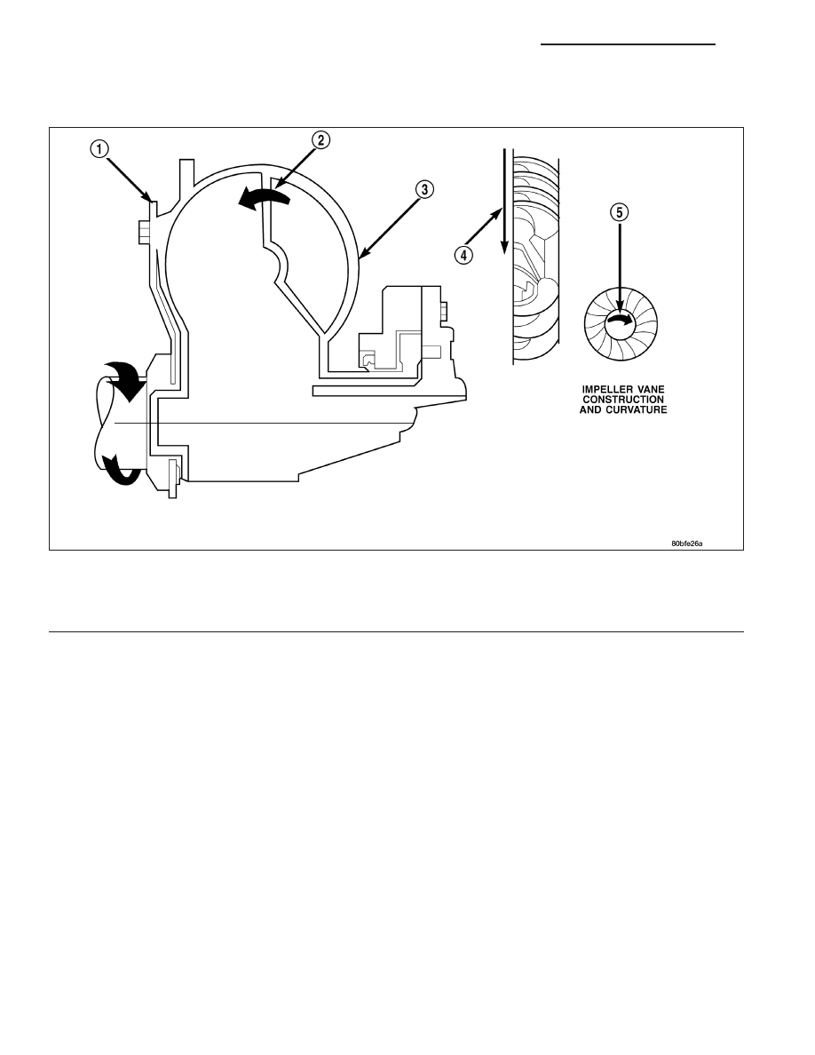
IMPELLER
The impeller (3) is an integral part of the converter housing. The impeller consists of curved blades placed radially
along the inside of the housing on the transmission side of the converter. As the converter housing is rotated by the
engine, so is the impeller, because they are one and the same and are the driving members of the system.
Impeller
1 - ENGINE FLEXPLATE
4 - ENGINE ROTATION
2 - OIL FLOW FROM IMPELLER SECTION INTO TURBINE
SECTION
5 - ENGINE ROTATION
3 - IMPELLER VANES AND COVER ARE INTEGRAL
21 - 454
AUTOMATIC TRANSMISSION NAG1 - SERVICE INFORMATION
LX