Chrysler 300/300 Touring/300C, Dodge Magnum. Manual - part 1944


  Index      Chrysler     Chrysler 300/300 Touring/300C, Dodge Magnum - service repair manual


Search            


Content   ..  1942  1943  1944  1945   ..


Chrysler 300/300 Touring/300C, Dodge Magnum. Manual - part 1944


15. Remove the output shaft bearing (3).

16. Remove the geartrain end-play shim from the out-

put shaft. Be sure to tag the shim since it is very
similar to the output shaft washer and they must
not be interchanged.

17. Remove the bolts holding the transmission housing to the converter housing from inside the converter housing.

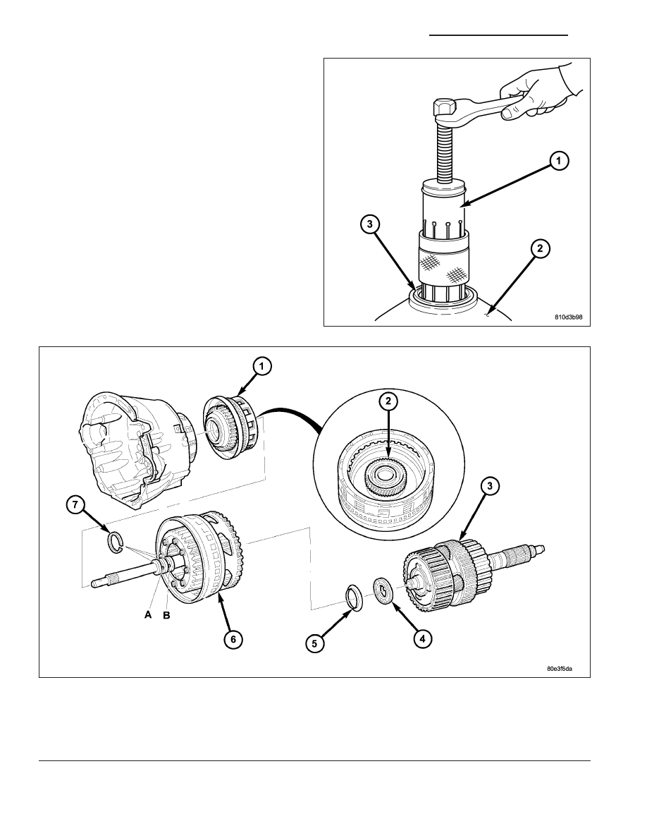
Remove K1, K2, and K3 Clutches

1 - DRIVING CLUTCH K1

5 - THRUST WASHER

2 - SUN GEAR OF FRONT PLANETARY GEAR SET

6 - FRONT PLANETARY GEAR SET, DRIVING CLUTCH K2, AND
INPUT SHAFT

3 - DRIVING CLUTCH K3, OUTPUT SHAFT , AND CENTER AND
REAR PLANETARY GEAR SETS

7 - SEALING RINGS

4 - THRUST NEEDLE BEARING

21 - 310

AUTOMATIC TRANSMISSION NAG1 - SERVICE INFORMATION

LX

18. Stand the transmission upright on the converter housing. Be sure to use suitable spacers between the bench

surface and the converter housing since the input shaft protrudes past the front surface of the housing.

19. Remove the remaining bolts holding the transmission housing to the converter housing.

20. Remove the transmission housing from the converter housing.

21. Remove output shaft with center and rear gear set and clutch K3 (3).

22. Remove thrust needle bearing (4) and thrust washer (5).

23. Remove input shaft with clutch K2 and front gear set (6).

24. Remove clutch K1 (1).

25. Unscrew Torx socket bolts (4) and remove oil pump (6). Screw two opposed bolts into the oil pump housing and

press the oil pump out of the converter housing by applying light blows with a plastic hammer.

26. Remove and discard the torque converter hub seal and the oil pump outer o-ring seal from the oil pump.

27. Unscrew Torx socket bolts (1) and remove multiple-disc holding clutch B1 (5) from converter housing. Screw

two opposed bolts into the multiple-disc holding clutch B1 (5) and separate from the converter housing by
applying light blows with a plastic hammer.

28. Detach intermediate plate (3) from converter housing (2).

Remove Holding Clutch B1 and Oil Pump

1 - BOLTS - M6X32

4 - BOLTS - M8X35

2 - CONVERTER HOUSING

5 - HOLDING CLUTCH B1

3 - INTERMEDIATE PLATE

6 - OIL PUMP

LX

AUTOMATIC TRANSMISSION NAG1 - SERVICE INFORMATION

21 - 311

29. Remove multiple-disc pack B3 (2) and spring washer (3) by removing snap-ring (1) in transmission housing. To

facilitate removal of the snap-ring (1), compress the multiple-disc pack B3 (2). Note which clutch disc is
removed just prior to the spring washer (3) for re-assembly. If the clutch discs are re-used, this disc must be
returned to its original position on top of the spring washer.

30. Unscrew Torx socket bolts (7).

31. Remove multiple-disc holding clutch B2 (4) from transmission housing. The externally toothed disc carrier for

multiple-disc holding clutch B2 is also the piston for multiple-disc holding clutch B3.

32. Remove parking lock gear (5).

ASSEMBLY

NOTE: If the transmission is being reconditioned (clutch/seal replacement) or replaced, it is necessary to
perform the TCM Adaptation Procedure using the scan tool (Refer to 8 - ELECTRICAL/ELECTRONIC CON-
TROL MODULES/TRANSMISSION CONTROL MODULE - STANDARD PROCEDURE).

Remove B2, B3, and Parking Gear

1 - SNAP-RING

5 - PARK GEAR

2 - HOLDING CLUTCH B3 DISCS

6 - TRANSMISSION HOUSING

3 - SPRING WASHER

7 - BOLTS - M8X60

4 - HOLDING CLUTCH B2

21 - 312

AUTOMATIC TRANSMISSION NAG1 - SERVICE INFORMATION

LX

1. Insert parking lock gear (5).

2. Install multiple-disc holding clutch B2 (4) in transmission housing (6).

3. Screw in both Torx socket bolts (7). Tighten the bolts to 16 N·m (141 in.lbs.).

NOTE: During the measurement the snap ring (7)
must contact the upper bearing surface of the
groove in the outer multiple-disc carrier (8).

NOTE: Pay attention to sequence of discs. If the
original clutch discs are reused, be sure to return
the disc identified on disassembly as belonging
on top of the spring washer (4) to its original loca-
tion. Place new friction multiple-discs in ATF fluid
for one hour before installing.

CAUTION: Apply only light pressure (less than 10
N (3 lbs.) of force) to the clutch pack when mea-
suring the clutch clearance with the feeler gauge.
Applying excessive force to the clutch will give an
incorrect reading and lead to a transmission fail-
ure.

4. Insert and measure spring washer (4) and multiple-

disc pack B3 (2, 6).

Install B2, B3, and Parking Gear

1 - SNAP-RING

5 - PARK GEAR

2 - HOLDING CLUTCH B3 DISCS

6 - TRANSMISSION HOUSING

3 - SPRING WASHER

7 - BOLTS - M8X60

4 - HOLDING CLUTCH B2

1 - OUTER DISC - 6.5 MM
(0.256 IN.)

5 - PISTON

2 - OUTER DISCS - 1.8 MM
(0.071 IN.)

6 - FRICTION DISCS

3 - OUTER DISCS - 1.8 MM
(0.071 IN.)

7 - SNAP-RING

4 - SPRING WASHER

8 - B3 DISC CARRIER

LX

AUTOMATIC TRANSMISSION NAG1 - SERVICE INFORMATION

21 - 313


Content   ..  1942  1943  1944  1945   ..