Content .. 1920 1921 1922 1923 ..
Chrysler 300/300 Touring/300C, Dodge Magnum. Manual - part 1922
P0562-BATTERY VOLTAGE LOW - ESM
For a complete wiring diagram Refer to Section 8W
Theory of Operation
The Shift Lever Assembly (SLA) controller (Electronic Shift Module - ESM) monitors ignition voltage. The DTC will
set if the monitored battery voltage drops below 6.0 volts and a temporary limp in will be activated. If the voltage
rises above 9.0 volts, normal operations is resumed.
•
When Monitored:
Continuously with the ignition on.
•
Set Condition:
When monitored battery voltage drops below 6.0 volts.
Possible Causes
VEHICLE CHARGING SYSTEM
(F902) IGNITION UNLOCK RUN START CIRCUIT
(Z911) GROUND CIRCUIT
SHIFT LEVER ASSEMBLY
Always perform the NAG1 Pre-Diagnostic Troubleshooting procedure before proceeding. (Refer to 21 -
TRANSMISSION/TRANSAXLE/AUTOMATIC - NAG1 - STANDARD PROCEDURE)
Diagnostic Test
1.
CHECK FOR ENGINE CHARGING SYSTEM DTCS
With the scan tool, read Engine DTCs.
Are there any Engine Charging System DTCs present?
Yes
>> Refer to 9 - ENGINE ELECTRICAL DIAGNOSTICS and perform the appropriate symptom.
Perform NAG1 TRANSMISSION VERIFICATION TEST. (Refer to 21 - TRANSMISSION/TRANSAXLE/
AUTOMATIC - NAG1 - STANDARD PROCEDURE)
No
>> Go To 3
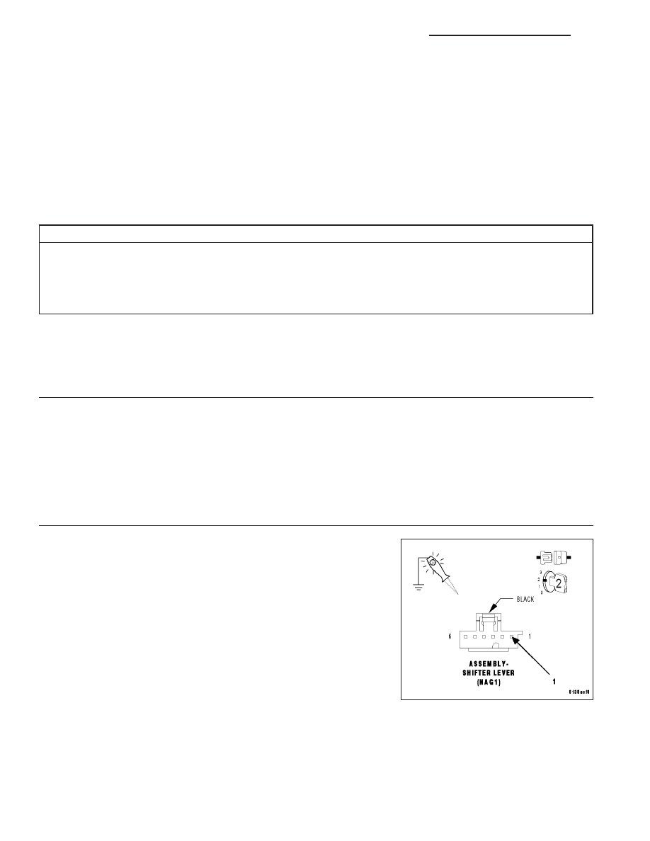
2.
CHECK (F902) IGNITION UNLOCK RUN START CIRCUIT
Turn the ignition off to the lock position.
Disconnect the Shift Lever Assembly harness connector.
Turn the ignition on.
Using a 12-volt test light connected to ground, check the (F902) Ignition
Unlock Run Start circuit in the Shift Lever Assembly harness connector.
NOTE: The test light must illuminate brightly. Compare the bright-
ness to that of a direct connection to the battery.
Does the test light illuminate brightly?
Yes
>> Go To 6
No
>> Repair the (F902) Ignition Unlock Run Start circuit for high
resistance.
Perform NAG1 TRANSMISSION VERIFICATION TEST.
(Refer to 21 - TRANSMISSION/TRANSAXLE/AUTOMATIC
- NAG1 - STANDARD PROCEDURE)
21 - 222
AUTOMATIC TRANSMISSION NAG1 - SHIFTER DIAGNOSTICS
LX