Chrysler 300/300 Touring/300C, Dodge Magnum. Manual - part 1845


  Index      Chrysler     Chrysler 300/300 Touring/300C, Dodge Magnum - service repair manual


Search            


Content   ..  1843  1844  1845  1846   ..


Chrysler 300/300 Touring/300C, Dodge Magnum. Manual - part 1845


GEAR

DESCRIPTION

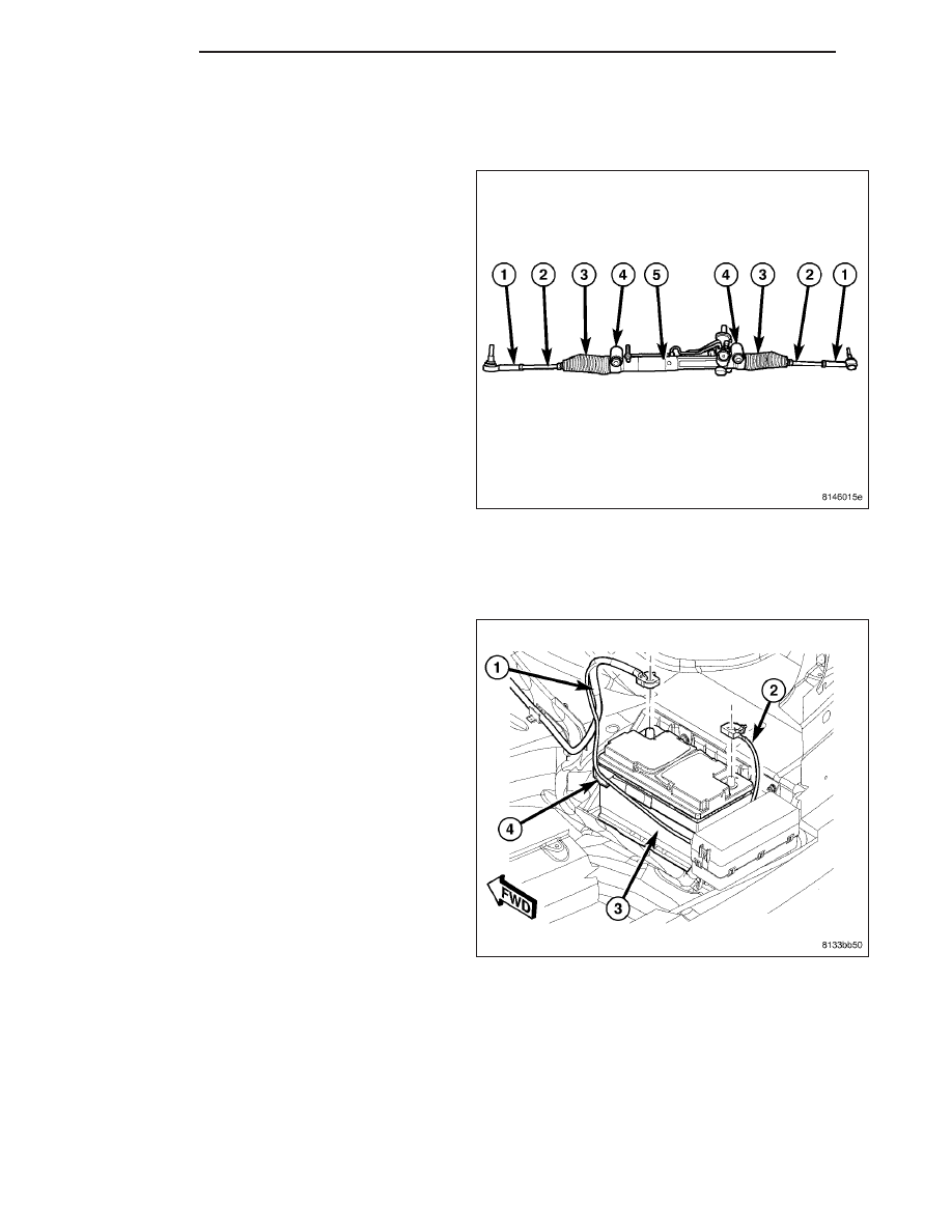
A power rack and pinion steering gear is used on both
AWD and RWD (shown) vehicles. Components of the
power steering gear are as follows:

(1) Outer tie rods

(2) Inner tie rods

(3) Bellows

(4) Mount Bushings

(5) Housing

The gear cannot be adjusted or internally serviced. If
a malfunction or a fluid leak occurs, the gear must be
replaced as an assembly. The only serviceable com-
ponent on the steering gear is the outer tie rod (1).

REMOVAL

AWD

1. Disconnect and isolate battery negative cable (2)

from battery post.

2. Siphon power steering fluid from pump reservoir.

3. Raise and support vehicle. (Refer to LUBRICATION

&

MAINTENANCE/HOISTING

-

STANDARD

PROCEDURE)

19 - 198

GEAR

LX

4. Remove wheel mounting nuts (3), then both front

tire and wheel assemblies (1).

CAUTION: When loosening jam nut and rotating
inner tie rod, use care not to twist bellows at inner
tie rod. Remove clamp (2) at inner tie rod and
make sure bellows moves freely before rotating
inner tie rod.

5. Loosen tie rod jam nut (1) at each outer tie rod (4).

6. Remove outer tie rod (2) end nut (1) at each

knuckle (3).

LX

GEAR

19 - 199

7. Using Remover (2), Special Tool 9360, separate

outer tie rod (1) from each knuckle.

8. Remove steering coupling pinch bolt at steering gear. (Refer to 19 - STEERING/COLUMN/STEERING COU-

PLING - REMOVAL)

9. Unthread return hose tube nut (1) from steering

gear (2). Remove return hose from steering gear.

10. Unthread pressure hose tube nut (3) from steering

gear (2). Remove pressure hose from steering
gear.

19 - 200

GEAR

LX

11. Remove mounting screws, then heat shield (3)

above each inner tie rod bellows (2).

12. Remove steering gear upper mounting bolt (4)

and nut.

13. Remove steering gear lower mounting bolts (2

and 3).

14. Remove steering gear (1).

15. If necessary, remove outer tie rods from gear.

Count number of revolutions off for each tie rod
for reference upon installation to replacement
gear.

LX

GEAR

19 - 201


Content   ..  1843  1844  1845  1846   ..