Content .. 1798 1799 1800 1801 ..
Chrysler 300/300 Touring/300C, Dodge Magnum. Manual - part 1800
4.
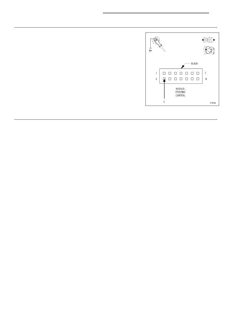
(Z910) GROUND CIRCUIT HIGH RESISTANCE
Using a 12–volt test light connected to 12–volts, check the (Z910)
Ground circuit in the Steering Control Module harness connector.
NOTE: The test light must illuminate brightly. Compare the bright-
ness to that of a direct connection to the battery.
Does the test light illuminate brightly?
Yes
>> Replace the Steering Control Module in accordance with
the Service Information.
No
>> Repair the (Z910) Ground circuit.
5.
INTERMITTENT BATTERY VOLTAGE LOW DTC
The conditions necessary to set this DTC are not present at this time.
Using the wiring diagram/schematic as a guide, inspect the wiring and connectors.
While monitoring the scan tool data relative to this circuit, wiggle test the wiring and connectors.
Look for the data to change or for the DTC to reset during the wiggle test.
Were any problems found?
Yes
>> Repair as necessary.
No
>> Test complete.
19 - 18
COLUMN ELECTRICAL DIAGNOSIS
LX