Chrysler 300/300 Touring/300C, Dodge Magnum. Manual - part 1789


  Index      Chrysler     Chrysler 300/300 Touring/300C, Dodge Magnum - service repair manual


Search            


Content   ..  1787  1788  1789  1790   ..


Chrysler 300/300 Touring/300C, Dodge Magnum. Manual - part 1789


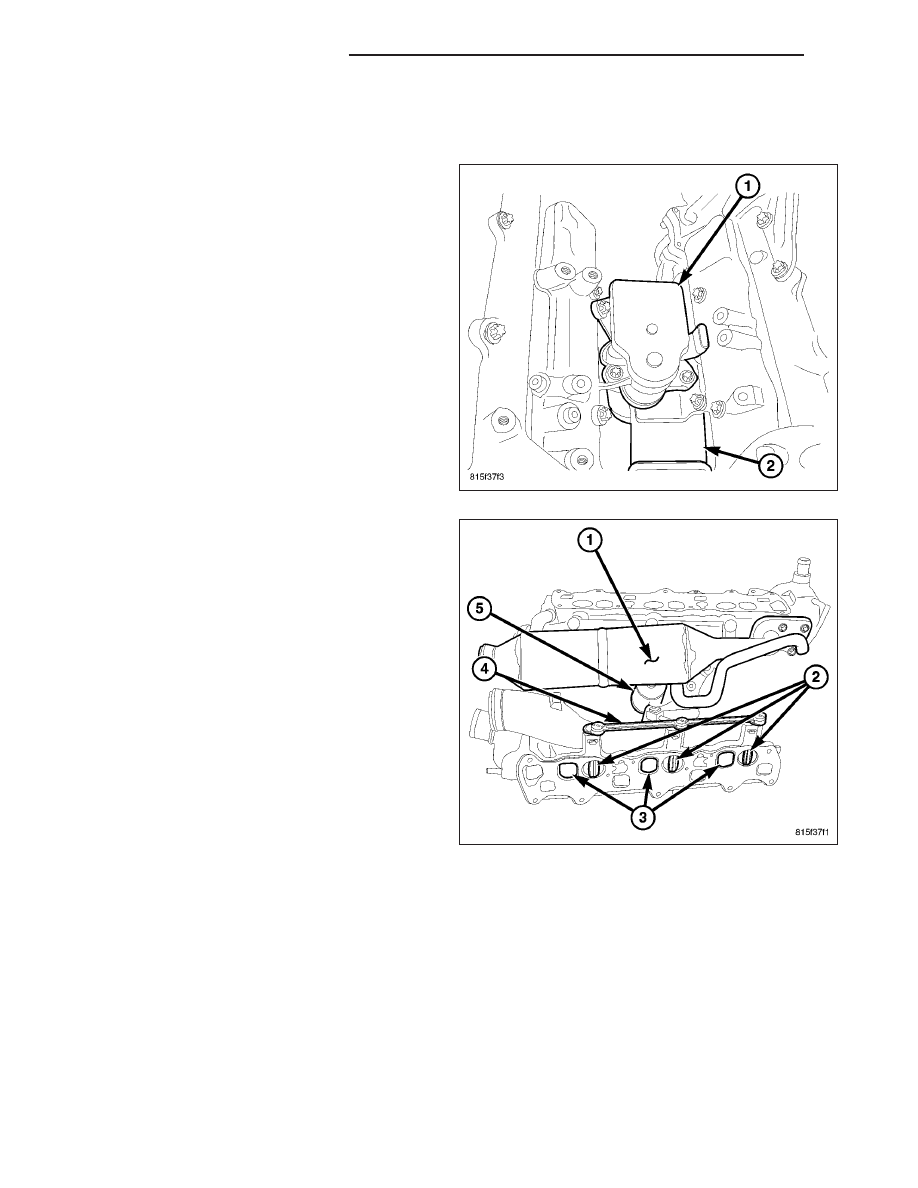
ACTUATOR-INTAKE PORT SWIRL

DESCRIPTION

The intake manifold swirl actuator is located between
the two intake manifolds.

The intake manifolds have a charge air passage (3)
which are ovate, and swirl passage (2) which are
round, for each cylinder. The swirl blades (2) are
mounted in each intake manifold swirl passage (2)
and are not serviceable. The actuator (5) is PWM con-
trolled by the ECM and is constantly adjusting while
the engine is running to optimize the air/fuel mixture
and create the best possible air turbulence. The result
is Improved combustion, improved engine perfor-
mance and a reduction in exhaust particulates. The
swirl blades (2) in the intake manifold are held in the
open position by an internal spring in an un-powered
state.

14 - 230

FUEL INJECTION - DIESEL

LX

OPERATION

There are two channels in each intake manifold for
each cylinder. A charge air intake passage (3) and a
swirl intake passage (2). The swirl passage (2) incor-
porates a blade (2) that is continually adjusted through
linkage (4) and an actuator (5) when ever the engine
is running. The actuator (5) is controlled by the ECM
through a PWM signal. As engine speed and load
increase the swirl channels adjust for optimized air tur-
bulence and air mass requirements. When the engine
is not running, the swirl channel blades (2) are held
open by and integrated spring.

REMOVAL

1. Disconnect the negative battery cable.

2. Remove the engine cover.

3. Remove the strut tower support.

4. Drain the cooling system.

5. Remove the intake manifold (Refer to 9 - ENGINE/

MANIFOLDS/INTAKE MANIFOLD - REMOVAL).

6. Position the intake manifolds on a work bench.

CAUTION: Care must be taken when disconnect-
ing the actuator and rod assembly. Failure to do
so will result in poor connections during assembly
or intake manifold replacement.

7. Pinch together the actuating rod retaining clip and

carefully separate the rod from the actuator.

8. Remove the actuator fasteners and actuator (1)

from the intake manifold.

LX

FUEL INJECTION - DIESEL

14 - 231

INSTALLATION

1. Position the actuator (1) on the intake manifold and

tighten fasteners to 12N·m (106 in. lbs.).

CAUTION: Care must be taken when connecting
the actuator and rod assembly. Failure to do so
will result in poor connections during assembly or
intake manifold replacement.

2. Carefully connect the relationship rod to the actua-

tor. Do Not Force.

3. Install the intake manifold (Refer to 9 - ENGINE/

MANIFOLDS/INTAKE

MANIFOLD

-

INSTALLA-

TION).

4. Install the turbocharger (Refer to 11 - EXHAUST

SYSTEM/TURBOCHARGER SYSTEM - INSTAL-
LATION).

5. Fill the cooling system using the appropriate

H.O.A.T. coolant.

WARNING: (Refer to 14 - FUEL SYSTEM - WARN-
ING)

6. Start the engine, allow to warm, turn engine off and inspect for leaks.

7. Install the engine cover.

8. Install the strut tower support.

14 - 232

FUEL INJECTION - DIESEL

LX

INJECTOR-FUEL

DESCRIPTION

There are individual fuel injectors for all six cylinders. These fuel injectors are used to spray fuel into the combustion
chamber. The injectors are indirectly controlled by piezo actuators that allow precise timing of up to five injections
with minimal drift values and stable minimum amounts. The injector nozzles have eight injection orifices which
allows for optimum fuel atomization. Each injector has a six digit alphanumeric code on the injector top which must
be entered into to ECM using the scan tool. Specific moving parts inside the injector are graphite coated to assist
with the lubrication process.

OPERATION

The injector operation can be subdivided into four
operating states with the engine running and the high-
pressure pump generating pressure:

Injector closed (with high pressure applied)

Injector opens (start of injection)

Injector opened fully

Injector closes (end of injection)

Injector closed (with high pressure applied)

With the injector closed (at-rest state), the solenoid valve is not energized and is therefore closed. With the bleed
orifice closed, the valve spring forces the armature’s ball onto the bleed-orifice seat. The rail’s high pressure build
up in the valve control chamber, and the same pressure is also present in the nozzle’s chamber volume. The rail
pressure applied at the control plunger’s end face, together with the force of the nozzle spring, maintain the nozzle
in the closed position against the opening forces applied to its pressure stage.

LX

FUEL INJECTION - DIESEL

14 - 233


Content   ..  1787  1788  1789  1790   ..