Content .. 1775 1776 1777 1778 ..
Chrysler 300/300 Touring/300C, Dodge Magnum. Manual - part 1777
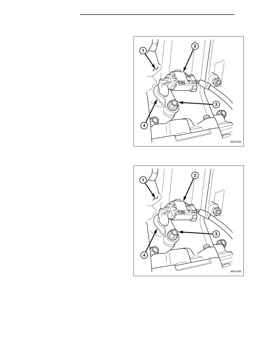
5.7L
1. Clean out machined hole in engine block.
2. Apply a small amount of engine oil to sensor
o-ring.
3. Install sensor (4) into engine block with a slight
rocking and twisting action.
CAUTION: Before tightening sensor mounting bolt
(3) , be sure sensor is completely flush to cylinder
block. If sensor is not flush, damage to sensor
mounting tang may result.
4. Install mounting bolt (3) and tighten to 12 N·m (106
in. lbs.) torque.
5. Connect electrical connector (2) to sensor.
6. Lower vehicle.
6.1L
1. Clean out machined hole in engine block.
2. Apply a small amount of engine oil to sensor
o-ring.
3. Install sensor (4) into engine block with a slight
rocking and twisting action.
CAUTION: Before tightening sensor mounting bolt
(3) , be sure sensor is completely flush to cylinder
block. If sensor is not flush, damage to sensor
mounting tang may result.
4. Install mounting bolt (3) and tighten to 12 N·m (106
in. lbs.) torque.
5. Connect electrical connector (2) to sensor.
6. IF STARTER IS MOUNTED TO RIGHT SIDE OF
ENGINE: Install starter motor.
7. Lower vehicle.
8. IF STARTER IS MOUNTED TO RIGHT SIDE OF
ENGINE: Install negative battery cable.
14 - 182
FUEL INJECTION
LX