Chrysler 300/300 Touring/300C, Dodge Magnum. Manual - part 1537


  Index      Chrysler     Chrysler 300/300 Touring/300C, Dodge Magnum - service repair manual


Search            


Content   ..  1535  1536  1537  1538   ..


Chrysler 300/300 Touring/300C, Dodge Magnum. Manual - part 1537


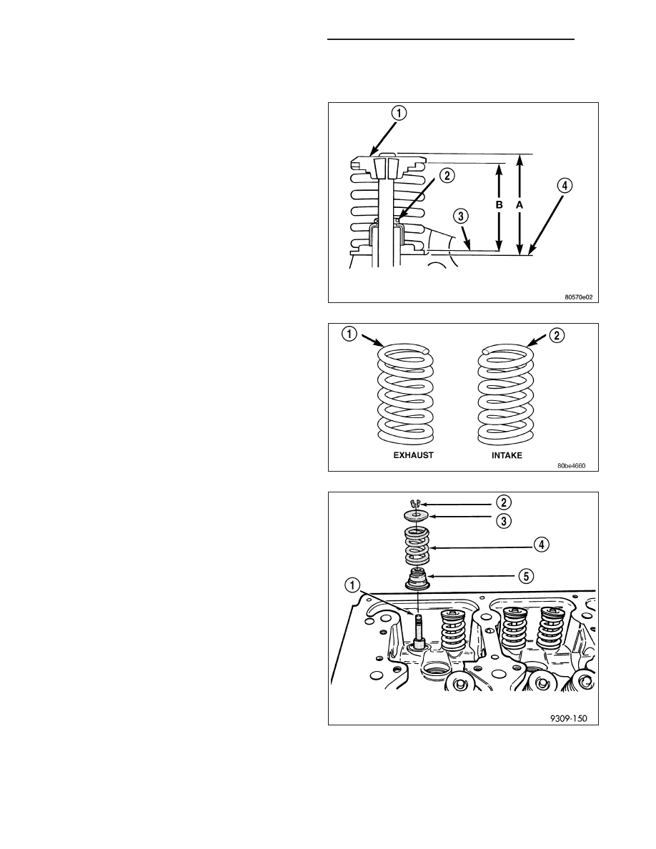
VALVE AND SPRING INSTALLED HEIGHT

1. Coat valve stems with clean engine oil and insert

them in cylinder head.

2. If valves or seats have been refaced, check valve

tip height (A). If valve tip height is greater than
43.65 mm (1.7185 in.) intake or 46.48 mm (1.8299
in.) exhaust, grind valve tip until within specifica-
tions. Make sure measurement is taken from cylin-
der head surface to the top of valve stem.

3. Install valve seal/spring seat assembly over valve

guides on all valve stem. Ensure that the garter
spring is intact around the top of the rubber seal.

4. Place valve spring (color-coded end facing up) and

valve retainer into position on spring seat.

5. Compress valve springs (4) with valve spring com-

pressor C-3422-D and adapter 6526 (Refer to 9 -
ENGINE - SPECIAL TOOLS), install locks (2) and
release tool.

6. If valves (1) and/or seats are refaced, measure the

installed height of springs. Measurements are
taken from top of spring (4) seat to the bottom sur-
face of spring retainer. If height is greater than
38.75 mm (1.5256 in.), install a 0.762 mm (0.030
in.) spacer in head counterbore under the valve
spring seat to bring spring height back within
specification.

9 - 2172

ENGINE - 3.5L - SERVICE INFORMATION

LX

REMOVAL

1. Remove cylinder head(s) (Refer to 9 - ENGINE/CYLINDER HEAD - REMOVAL).

2. Remove rocker arm assembly (Refer to 9 - ENGINE/CYLINDER HEAD/ROCKER ARM / ADJUSTER ASSY -

REMOVAL).

3. Remove valve spring(s) (Refer to 9 - ENGINE/CYLINDER HEAD/VALVE SPRINGS - REMOVAL).

4. Before removing valve, remove any burrs from valve stem lock grooves to prevent damage to the valve

guides. Identify valves to insure installation in original location.

5. Remove valve(s) from cylinder head.

CLEANING

1. Clean all valves thoroughly and discard burned, warped and cracked valves.

INSPECTION

VALVES

1. Measure valve stems for wear approximately 60

mm (2.36 in.) below the valve lock grooves.

2. Compare measurement to specifications, (Refer to

9 - ENGINE - SPECIFICATIONS).

NOTE: Valve stems are chrome plated and should
not be polished.

VALVE GUIDES

1. Measure valve stem-to-guide clearance as follows:

2. Install valve into cylinder head so it is 15 mm

(0.590 inch.) off the valve seat. A small piece of
hose may be used to hold valve in place.

3. Attach dial indicator Tool C-3339 to cylinder head

and set it at right angle of valve stem being mea-
sured.

4. Move valve to and from the indicator.

5. Note dial indicator reading and compare to engine

specifications. (Refer to 9 - ENGINE - SPECIFICA-
TIONS)

NOTE: Replace cylinder head if stem-to-guide
clearance exceeds specifications, or if guide is
loose in cylinder head.

LX

ENGINE - 3.5L - SERVICE INFORMATION

9 - 2173

INSTALLATION

1. Coat valve stems with clean engine oil and insert

them in cylinder head.

2. If valves or seats have been reground, check valve

tip height (A). If valve tip height is greater than
43.65 mm (1.7185 in.) intake or 46.48 mm (1.8299
in.) exhaust, grind valve tip until within specifica-
tions. Make sure measurement is taken from cylin-
der head surface to the top of valve stem.

3. Install new valve stem seals.

4. Install valve springs (Refer to 9 - ENGINE/CYLIN-

DER HEAD/VALVE SPRINGS - INSTALLATION).

5. Install cylinder head(s) (Refer to 9 - ENGINE/CYL-

INDER HEAD - INSTALLATION).

9 - 2174

ENGINE - 3.5L - SERVICE INFORMATION

LX

ROCKER ARM SHAFT/ ROCKER ARM / LASH ADJUSTER

DESCRIPTION

ROCKER ARM

Rocker arms are made of light weight permanent mold
aluminum alloy with a roller (3) type follower operating
against the camshaft. The valve actuating end of the
rocker arms are machined to retain hydraulic lash
adjusters, eliminating the need for manual valve lash
adjustment.

ROCKER ARM SHAFTS

The rocker arm shafts are tubular steel and are sup-
ported by several forged aluminum alloy pedestals,
which are fastened to the cylinder head. Four shafts
are used, one for each intake and exhaust rocker arm
bank on each cylinder head. The shafts are hollow to
provide a duct for lubricating oil flow from the cylinder
head to the valve mechanisms. One hollow dowel per
pedestal is used to locate the pedestal to the cylinder
head, orient the exhaust rocker shaft, and serve as a
cam bearing oil feed passage.

OPERATION

The rocker arm is the pivot point between the camshaft lobe and the valve.

DIAGNOSIS AND TESTING

LASH ADJUSTER (TAPPET) NOISE DIAGNOSIS

Proper noise diagnosis is essential in locating the source of a NVH complaint. Locating a lash adjuster (tappet) type
noise can sometimes be difficult. As a result, an initial misdiagnosis may occur.

Refer to the following chart indicating possible lash adjuster (tappet) noise sources and possible sources that could
lead to a misdiagnosis.

LX

ENGINE - 3.5L - SERVICE INFORMATION

9 - 2175


Content   ..  1535  1536  1537  1538   ..