Content .. 1404 1405 1406 1407 ..
Chrysler 300/300 Touring/300C, Dodge Magnum. Manual - part 1406
3.
(N117) INTAKE SWIRL SERVO MOTOR CONTROL CIRCUIT SHORTED TO THE (K343) FUSED ASD
RELAY OUTPUT 2 CIRCUIT
Turn the ignition off.
Measure the resistance between the (N117) Intake Swirl Servo Motor
Control circuit and the (K343) Fused ASD Relay Output 2 circuit in the
Intake Swirl Servo Motor connector.
Is the resistance above 10.0 ohms?
Yes
>> Go to 4
No
>> Repair the (N117) Intake Swirl Servo Motor Control circuit
for a short to the (K343) Fused ASD Relay Output 2 circuit.
Perform the ECM Verification Test Ver. 1. (Refer to 9 -
ENGINE - DIAGNOSIS AND TESTING)
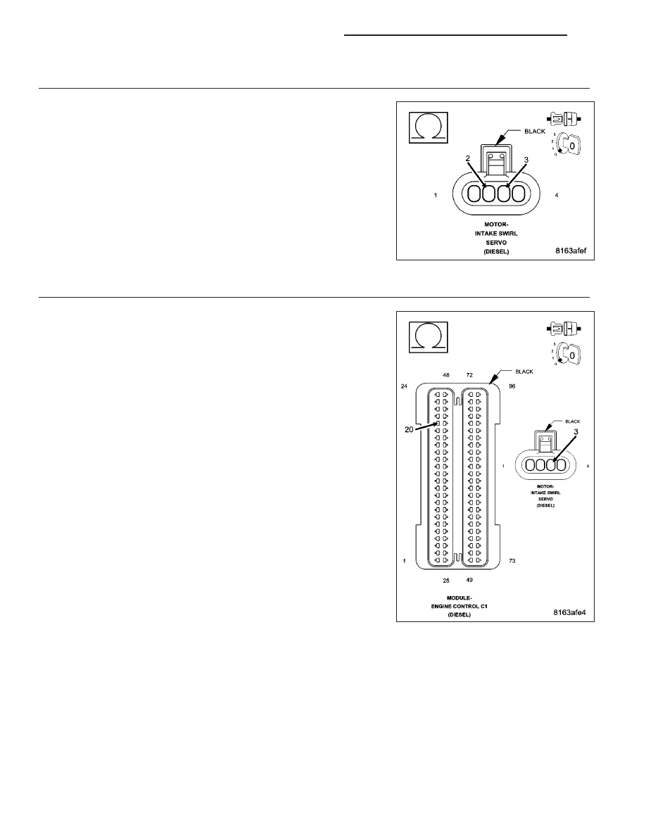
4.
(N117) INTAKE SWIRL SERVO MOTOR CONTROL CIRCUIT OPEN OR HIGH RESISTANCE
Measure the resistance of the (N117) Intake Swirl Servo Motor Control
circuit between the Intake Swirl Servo Motor connector and the Engine
Control Module (ECM) connector.
Is the resistance below 10.0 ohms?
Yes
>> Go to 5
No
>> Repair the (N117) Intake Swirl Servo Motor Control circuit
for an open circuit or high resistance.
Perform the ECM Verification Test Ver. 1. (Refer to 9 -
ENGINE - DIAGNOSIS AND TESTING)
9 - 1648
ENGINE ELECTRICAL DIAGNOSTICS - DIESEL
LX