Chrysler 300/300 Touring/300C, Dodge Magnum. Manual - part 1350


  Index      Chrysler     Chrysler 300/300 Touring/300C, Dodge Magnum - service repair manual


Search            


Content   ..  1348  1349  1350  1351   ..


Chrysler 300/300 Touring/300C, Dodge Magnum. Manual - part 1350
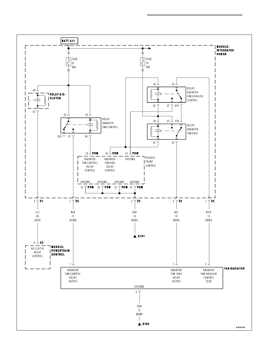


P0480-COOLING FAN 1 CONTROL CIRCUIT

For a complete wiring diagram Refer to Section 8W.

9 - 1424

ENGINE ELECTRICAL DIAGNOSTICS - DIESEL

LX

When Monitored:
With the ignition on. Battery voltage greater than 10 volts.

Set Condition:
The ECM receives a CAN Bus message from the FCM indicating an open or shorted circuit on the Radiator
Fan Relay Control circuit.

Possible Causes

FUSED (B+) FEED CIRCUITS

(N201) RADIATOR FAN CONTROL RELAY CONTROL CIRCUIT OPEN

(N201) RADIATOR FAN CONTROL RELAY CIRCUIT SHORT TO GROUND

RADIATOR FAN CONTROL RELAY

FRONT CONTROL MODULE

Always perform the Pre-Diagnostic Troubleshooting procedure before proceeding. (Refer to 9 - ENGINE -
DIAGNOSIS AND TESTING).

Diagnostic Test

1.

RADIATOR FAN CONTROL RELAY OPERATION

NOTE: When actuating the radiator fan relays, the Radiator Fan(s) may have a delay in operation and ramp
up slowly.
Ignition on, engine not running.

With a scan tool, select Radiator Cooling Fan Relay #1 Control State to actuate the Radiator Fan Control Relay.

Is the Cooling Fan Relay operating?

Yes

>> Refer to the *CHECKING FOR AN INTERMITTENT DTC Diagnostic Procedure. (Refer to 9 - ENGINE -

DIAGNOSIS AND TESTING)

Perform the ECM Verification Test Ver. 1. (Refer to 9 - ENGINE - DIAGNOSIS AND TESTING)

No

>> Go To 2

2.

FUSED B+ CIRCUITS

Turn the ignition off.

Remove the Radiator Fan Control Relay.

Using a 12-volt test light connected to ground, probe the Fused B+ cir-
cuits.

Is the voltage above 11.0 volts?

Yes

>> Go To 3

No

>> Repair the open or short to ground in the Fused B+ circuits.

Inspect the related fuse and repair as necessary.

Perform BODY VERIFICATION TEST – VER 1. (Refer to 8
-

ELECTRICAL/ELECTRONIC

CONTROL MODULES

-

STANDARD PROCEDURE)

LX

ENGINE ELECTRICAL DIAGNOSTICS - DIESEL

9 - 1425

3.

RADIATOR FAN CONTROL RELAY CONTROL CIRCUIT

Turn the ignition on, engine not running.

With a scan tool, select Radiator Cooling Fan Relay #1 Control State,
Toggle, to actuate the Radiator Fan Control Relay.

Using a 12–volt test light connected to battery voltage, probe the Radi-
ator Control Relay Control circuit in the PDM.

Does the test light illuminate and flash on and off?

Yes

>> Replace the Radiator Fan Control Relay.

Perform BODY VERIFICATION TEST – VER 1. (Refer to 8
-

ELECTRICAL/ELECTRONIC

CONTROL MODULES

-

STANDARD PROCEDURE)

No

>> Go To 4

4.

(N201) RADIATOR FAN CONTROL RELAY CONTROL CIRCUIT OPEN

Turn the ignition off.

Remove the FCM from the PDM.

Measure the resistance of the (N201) Radiator Fan Control Relay Con-
trol circuit from the Relay to the FCM PDM — 49 way connector.

Is the resistance below 5.0 ohms?

Yes

>> Go To 5

No

>> Replace the PDM in accordance with the Service informa-

tion.

Perform BODY VERIFICATION TEST – VER 1. (Refer to 8
-

ELECTRICAL/ELECTRONIC

CONTROL MODULES

-

STANDARD PROCEDURE)

5.

(N201) RADIATOR FAN CONTROL RELAY CONTROL CIRCUIT SHORTED TO GROUND

Measure the resistance between ground and the (N201) Radiator Fan
Control Relay Control circuit at the Relay connection.

Is the resistance below 100 ohms?

Yes

>> Replace the PDM in accordance with the Service informa-

tion.

Perform BODY VERIFICATION TEST – VER 1. (Refer to 8
-

ELECTRICAL/ELECTRONIC

CONTROL MODULES

-

STANDARD PROCEDURE)

No

>> Replace Front Control Module in accordance with the Ser-

vice Information.

Perform BODY VERIFICATION TEST – VER 1. (Refer to 8
-

ELECTRICAL/ELECTRONIC

CONTROL MODULES

-

STANDARD PROCEDURE)

9 - 1426

ENGINE ELECTRICAL DIAGNOSTICS - DIESEL

LX

P0481-COOLING FAN 2 CONTROL CIRCUIT

For a complete wiring diagram Refer to Section 8W.

LX

ENGINE ELECTRICAL DIAGNOSTICS - DIESEL

9 - 1427


Content   ..  1348  1349  1350  1351   ..