Chrysler 300/300 Touring/300C, Dodge Magnum. Manual - part 1346


  Index      Chrysler     Chrysler 300/300 Touring/300C, Dodge Magnum - service repair manual


Search            


Content   ..  1344  1345  1346  1347   ..


Chrysler 300/300 Touring/300C, Dodge Magnum. Manual - part 1346


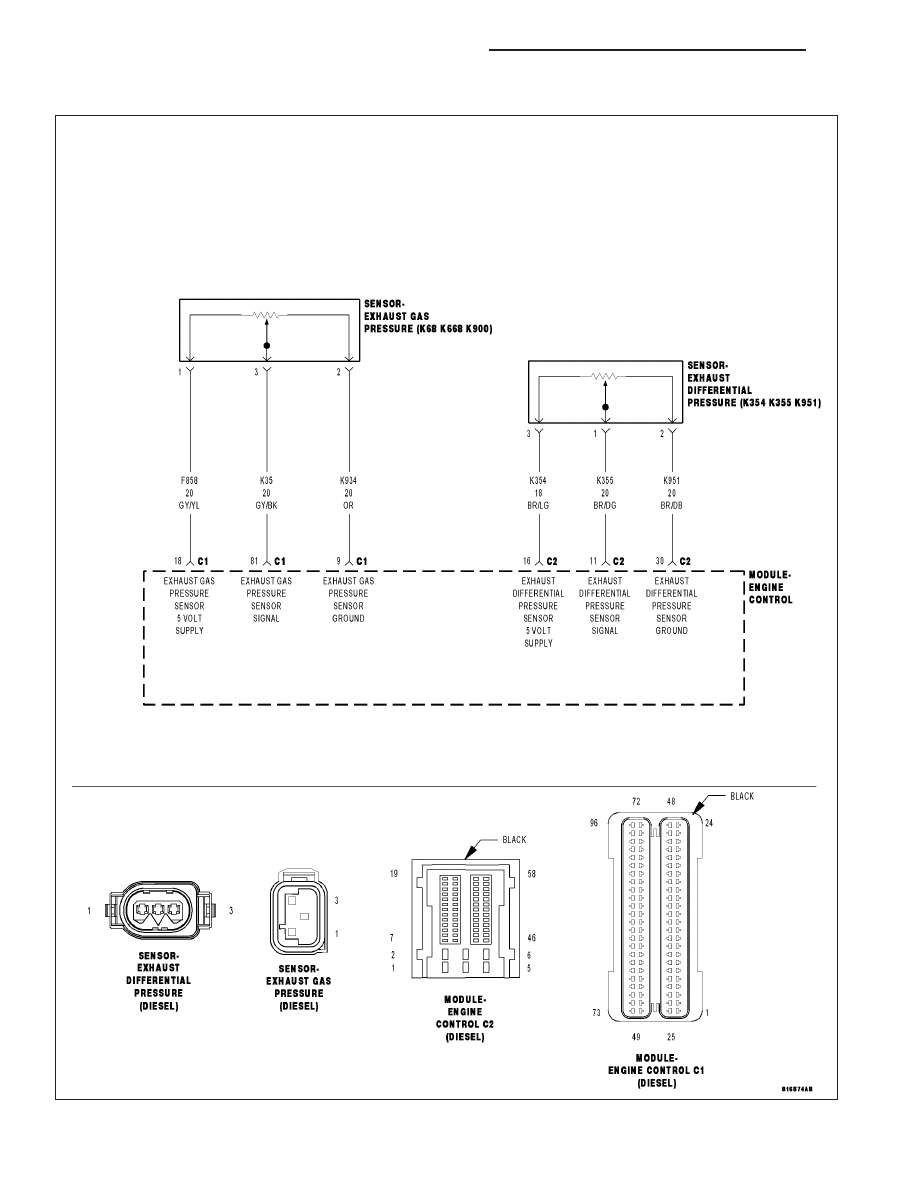
P0471-EXHAUST PRESSURE SENSOR 1 PERFORMANCE

For a complete wiring diagram Refer to Section 8W

9 - 1408

ENGINE ELECTRICAL DIAGNOSTICS - DIESEL

LX

The Inlet Pressure Sensor provides the ECM with the Barometric/Atmospheric Pressure signal. The ECM compares
the Atmospheric/Barometric signal to the signal of the Exhaust Pressure Sensor during low engine rpm (non-turbo-
charger boost conditions) to determine the plausibility of these sensors.

When Monitored:
Engine speed is below 670 rpm. There are no other Exhaust Pressure Sensor DTC’s. There are no Atmo-
spheric/Barometric Pressure Sensor DTC’s..

Set Condition:
The difference between the Exhaust Pressure Sensor Signal and the Atmospheric/Barometric Pressure Signal
is greater than 400 hpa (5.8 psi.) for at least 3.0 seconds.

Possible Causes

INTERMITTENT DTC

(F858) EXHAUST GAS PRESSURE SENSOR 5 VOLT SUPPLY CIRCUIT SHORTED TO VOLTAGE

(K35) EXHAUST GAS PRESSURE SENSOR SIGNAL CIRCUIT SHORTED TO VOLTAGE

(K934) EXHAUST GAS PRESSURE SENSOR GROUND CIRCUIT SHORTED TO VOLTAGE

(F858) EXHAUST GAS PRESSURE SENSOR 5 VOLT SUPPLY CIRCUIT SHORTED TO GROUND

(K35) EXHAUST GAS PRESSURE SENSOR SIGNAL CIRCUIT SHORTED TO GROUND

(F858) EXHAUST GAS PRESSURE SENSOR 5 VOLT SUPPLY CIRCUIT OPEN OR HIGH RESISTANCE

(K35) EXHAUST GAS PRESSURE SENSOR SIGNAL CIRCUIT OPEN OR HIGH RESISTANCE

(K934) EXHAUST GAS PRESSURE SENSOR GROUND CIRCUIT OPEN OR HIGH RESISTANCE

EXHAUST GAS PRESSURE SENSOR

ENGINE CONTROL MODULE (ECM)

Always perform the Pre-Diagnostic Troubleshooting procedure before proceeding. (Refer to 9 - ENGINE -
DIAGNOSIS AND TESTING)

Diagnostic Test

1.

DTC IS ACTIVE

Ignition on, engine not running.

With the scan tool, Clear DTCs in the Engine Control Module (ECM).

Monitor the scan tool for at least two minutes.

Cycle the ignition key off and on several times, leaving the ignition on for at least 10 seconds at a time.

Start the engine.

Allow the engine to reach normal operating temperature.

With the scan tool, select View DTCs.

Is the status Active for this DTC?

Yes

>> Go To 2

No

>> Refer to the *CHECKING FOR AN INTERMITTENT DTC Diagnostic Procedure. (Refer to 9 - ENGINE -

DIAGNOSIS AND TESTING)

LX

ENGINE ELECTRICAL DIAGNOSTICS - DIESEL

9 - 1409

2.

EXHAUST GAS PRESSURE SENSOR CIRCUIT SHORTED TO VOLTAGE

Turn the ignition off.

Disconnect the Exhaust Gas Pressure Sensor connector.

Disconnect the Engine Control Module (ECM) connector.

Remove the ASD Relay from the IPM.

Connect a jumper wire between cavity 30 and cavity 87 of the ASD
Relay Connector.

Turn the ignition on.

Measure the voltage of the (F858) Exhaust Gas Pressure Sensor 5 Volt
Supply circuit in the Exhaust Gas Pressure Sensor connector.

Measure the voltage of the (K35) Exhaust Gas Pressure Sensor Signal
circuit in the Exhaust Gas Pressure Sensor connector.

Measure the voltage of the (K934) Exhaust Gas Pressure Sensor
Ground circuit in the Exhaust Gas Pressure Sensor connector.

Is there voltage present on any of the circuits?

Yes

>> Repair the circuit that had voltage present on it for a short to voltage.

Perform the ECM Verification Test Ver. 1. (Refer to 9 - ENGINE - DIAGNOSIS AND TESTING)

No

>> Go to 3

3.

EXHAUST GAS PRESSURE SENSOR CIRCUIT OPEN OR HIGH RESISTANCE

Turn the ignition off.

Disconnect the Engine Control Module (ECM) connector.

Measure the resistance of the (F858) Exhaust Gas Pressure Sensor 5
Volt Supply circuit between the Exhaust Gas Pressure Sensor connec-
tor and the Engine Control Module (ECM) connector.

Measure the resistance of the (K35) Exhaust Gas Pressure Sensor Sig-
nal circuit between the Exhaust Gas Pressure Sensor connector and
the Engine Control Module (ECM) connector.

Measure the resistance of the (K934) Exhaust Gas Pressure Sensor
Ground circuit between the Exhaust Gas Pressure Sensor connector
and the Engine Control Module (ECM) connector.

Is the resistance below 10.0 ohms for each of the circuits?

Yes

>> Go to 4

No

>> Repair the circuit that measure above 10.0 ohms for an

open circuit or high resistance.

Perform the ECM Verification Test Ver. 1. (Refer to 9 -
ENGINE - DIAGNOSIS AND TESTING)

9 - 1410

ENGINE ELECTRICAL DIAGNOSTICS - DIESEL

LX

4.

EXHAUST GAS PRESSURE SENSOR CIRCUIT SHORTED TO GROUND

Measure the resistance between ground and the (F858) Exhaust Gas
Pressure Sensor 5 Volt Supply circuit in the Exhaust Gas Pressure Sen-
sor connector.

Measure the resistance between ground and the (K35) Exhaust Gas
Pressure Sensor Signal circuit in the Exhaust Gas Pressure Sensor
connector.

Is the resistance between ground and each circuit above 1000
ohms?

Yes

>> Go to 5

No

>> Repair the circuit that measured below 1000 ohms for a

short to ground.

Perform the ECM Verification Test Ver. 1. (Refer to 9 -
ENGINE - DIAGNOSIS AND TESTING)

5.

EXHAUST GAS PRESSURE SENSOR

Turn the ignition off.

Remove the jumper wire and install the ASD Relay.

Connect the Engine Control Module (ECM) connector.

Connect a jumper wire between the (K934) Exhaust Gas Pressure Sensor Ground circuit and the (K35) Exhaust
Gas Pressure Sensor Signal circuit in the Exhaust Gas Pressure Sensor connector.

Turn the ignition on.

With the scan tool, Clear DTCs.

With the scan tool, select View DTCs.

NOTE: The scan tool should display an Exhaust Gas Pressure Sensor low voltage or short to ground DTC
with the jumper wire in place.
Turn the ignition off.

Remove the jumper wire.

Turn the ignition on.

With the scan tool, Clear DTCs.

With the scan tool, select View DTCs.

NOTE: The scan tool should display an Exhaust Gas Pressure Sensor high voltage or open DTC with the
Exhaust Gas Pressure Sensor connector disconnected.

Does the scan tool display the DTC(s) as described above?

Yes

>> Replace the Exhaust Gas Pressure Sensor.

Perform the ECM Verification Test Ver. 1. (Refer to 9 - ENGINE - DIAGNOSIS AND TESTING)

No

>> Go to 6

LX

ENGINE ELECTRICAL DIAGNOSTICS - DIESEL

9 - 1411


Content   ..  1344  1345  1346  1347   ..