Content .. 1341 1342 1343 1344 ..
Chrysler 300/300 Touring/300C, Dodge Magnum. Manual - part 1343
•
When Monitored:
With the ignition on.
•
Set Condition:
The ECM does not receive a valid fuel level signal message from the Instrument Cluster (CCN) for 2.0 sec-
onds.
Possible Causes
INTERMITTENT DTC
(N4) FUEL LEVEL SENSOR NO. 1 SIGNAL CIRCUIT SHORTED TO VOLTAGE
(Z210) GROUND CIRCUIT SHORTED TO VOLTAGE
(N4) FUEL LEVEL SENSOR NO. 1 SIGNAL CIRCUIT SHORTED TO GROUND
(N4) FUEL LEVEL SENSOR NO. 1 SIGNAL CIRCUIT SHORTED TO (Z210) GROUND CIRCUIT
(N4) FUEL LEVEL SENSOR NO. 1 SIGNAL CIRCUIT OPEN OR HIGH RESISTANCE
(Z210) GROUND CIRCUIT OPEN OR HIGH RESISTANCE
FUEL LEVEL SENSOR
INSTRUMENT CLUSTER (CCN)
Always perform the Pre-Diagnostic Troubleshooting procedure before proceeding. (Refer to 9 - ENGINE -
DIAGNOSIS AND TESTING)
Diagnostic Test
1.
DTC IS ACTIVE
Ignition on, engine not running.
With the scan tool, Clear DTCs in the Instrument Cluster (CCN).
Monitor the scan tool for at least two minutes.
Cycle the ignition key off and on several times, leaving the ignition on for at least 10 seconds at a time.
Start the engine.
Allow the engine to reach normal operating temperature.
With the scan tool, select View DTCs.
Is the status Active for this DTC?
Yes
>> Go To 2
No
>> Refer to the *CHECKING FOR AN INTERMITTENT DTC Diagnostic Procedure. (Refer to 9 - ENGINE -
DIAGNOSIS AND TESTING)
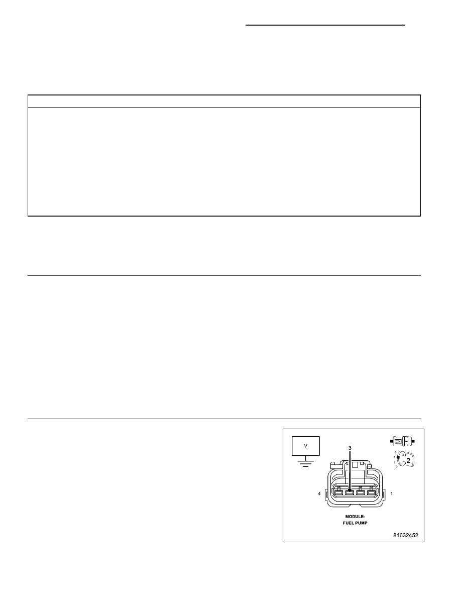
2.
(N4) FUEL LEVEL SENSOR NO. 1 SIGNAL CIRCUIT SHORTED TO VOLTAGE
Turn the ignition off.
Disconnect the Fuel Pump connector.
Disconnect the Instrument Cluster (CCN) connector.
Turn the ignition on.
Measure the voltage of the (N4) Fuel Level Sensor No. 1 Signal circuit
in the Fuel Pump connector.
Is there any voltage present?
Yes
>> Repair the (N4) Fuel Level Sensor No. 1 Signal circuit for a
short to voltage.
Perform the BODY VERIFICATION TEST VER 1. (Refer to
8 - ELECTRICAL/ELECTRONIC CONTROL MODULES -
STANDARD PROCEDURE)
No
>> Go to 3
9 - 1396
ENGINE ELECTRICAL DIAGNOSTICS - DIESEL
LX