Chrysler 300/300 Touring/300C, Dodge Magnum. Manual - part 1193


  Index      Chrysler     Chrysler 300/300 Touring/300C, Dodge Magnum - service repair manual


Search            


Content   ..  1191  1192  1193  1194   ..


Chrysler 300/300 Touring/300C, Dodge Magnum. Manual - part 1193


When Monitored:
With the ignition on and no other DTCs present for TP Sensor No.1 or No.2.

Set Condition:
PCM recognizes TP Sensors No.1 and No.2 are not coherent. One trip fault and the code will set within 5
seconds. ETC light is illuminated.

Possible Causes

(K22) TP SENSOR NO.1 OR (K122) TP SENSOR NO.2 SIGNAL CIRCUIT SHORTED TO BATTERY VOLTAGE

RESISTANCE IN THE (K22) TP SENSOR NO.1 OR (K122) TP SENSOR NO.2 SIGNAL CIRCUIT

(K22) TP SENSOR NO.1 OR (K122) TP SENSOR NO.2 SIGNAL CIRCUIT SHORTED TO GROUND

RESISTANCE IN (F855) 5-VOLT SUPPLY CIRCUIT

(F855) 5-VOLT SUPPLY CIRCUIT SHORTED TO GROUND

RESISTANCE IN THE (K922) SENSOR GROUND CIRCUIT

(K22) TP SENSOR NO.1 SIGNAL CIRCUIT SHORTED TO (K122) TP SENSOR NO.2 SIGNAL CIRCUIT

THROTTLE POSITION SENSOR

PCM

Always perform the Pre-Diagnostic Troubleshooting procedure before proceeding. (Refer to 9 - ENGINE -
DIAGNOSIS AND TESTING).

Diagnostic Test

1.

ACTIVE DTC

NOTE: The throttle plate and linkage should be free from binding and carbon build up.

NOTE: Make sure the throttle plate is at the idle position.
Ignition on, engine not running.

NOTE: Inspect the engine for vacuum leaks.
With a scan tool, read DTCs.

Is the DTC active at this time?

Yes

>> Go To 2

No

>> Go To 11

2.

(K22) TP SENSOR NO.1 OR (K122) TP SENSOR NO.2 SIGNAL CIRCUIT SHORTED TO BATTERY
VOLTAGE

Turn the ignition off.

Disconnect the PCM harness connector.

Disconnect the Throttle Body harness connector.

Ignition on, engine not running.

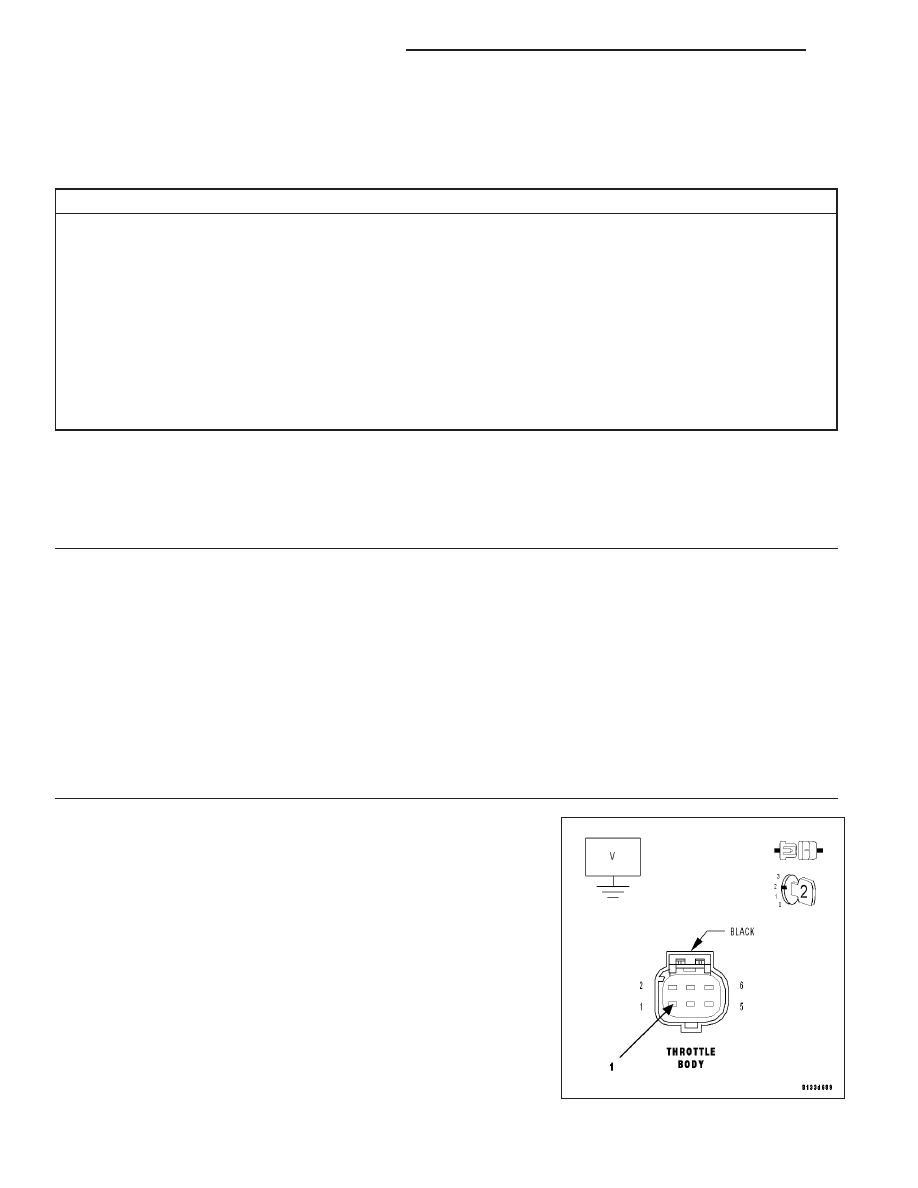
Measure the voltage on the (K22) TP No.1 Signal and the (K122) TP
No.2 Signal circuits in the Throttle Body harness connector.

Is the voltage above 5.2 volts?

Yes

>> Repair the short to battery voltage in the (K22) TP Sensor

No.1 or (K122) TP Sensor No.2 Signal circuit.

Perform the POWERTRAIN VERIFICATION TEST. (Refer
to 9 - ENGINE - STANDARD PROCEDURE)

No

>> Go To 3

9 - 796

ENGINE ELECTRICAL DIAGNOSTICS

LX

3.

THROTTLE POSITION SENSOR

Turn the ignition off.

Connect the PCM harness connector.

Ignition on, engine not running.

With a scan tool, monitor the TP Sensor No.1 and No.2 voltage.

Connect a jumper wire between the (K922) Sensor Return circuit and
the (K22) TP Sensor No.1 Signal circuit.

TP Sensor No.1 voltage should change from approximately 4.5 volts to
0.5 of a volt?

For TP Sensor No.2, connect a jumper wire between (F855) 5-volt sup-
ply circuit and the (K122) TP Sensor No.2 signal circuit.

TP Sensor No.2 voltage should change from approximately 0 volts to
5.0 volts?

Is the voltage reading within the listed specification with the
jumper wire installed?

Yes

>> Replace the Throttle Body Assembly.

Perform the POWERTRAIN VERIFICATION TEST. (Refer
to 9 - ENGINE - STANDARD PROCEDURE)

No

>> Go To 4

NOTE: Remove the jumper wire before continuing.

LX

ENGINE ELECTRICAL DIAGNOSTICS

9 - 797

4.

EXCESSIVE RESISTANCE IN THE (K22) TP SENSOR NO.1 OR (K122) TP SENSOR NO.2 SIGNAL CIRCUIT

Turn the ignition off.

Disconnect the PCM harness connector.

CAUTION: Do not probe the PCM harness connectors. Probing the
PCM harness connectors will damage the PCM terminals resulting
in poor terminal to pin connection. Install Miller Special Tool #8815
to perform diagnosis.
Measure the resistance of the (K22) TP Sensor No.1 Signal circuit from
the Throttle Body harness connector to the appropriate terminal of spe-
cial tool #8815.Measure the resistance of the (K122) TP Sensor No.2
Signal circuit from the Throttle Body harness connector to the appropri-
ate terminal of special tool #8815.

Is the resistance below 5.0 ohms for each circuit?

Yes

>> Go To 5

No

>> Repair the excessive resistance in the (K22) TP Sensor

No.1 or (K122) TP Sensor No.2 Signal circuit.

Perform the POWERTRAIN VERIFICATION TEST. (Refer
to 9 - ENGINE - STANDARD PROCEDURE)

9 - 798

ENGINE ELECTRICAL DIAGNOSTICS

LX

5.

(K22) TP SENSOR NO.1 OR (K122) TP SENSOR NO.1 SIGNAL CIRCUIT SHORTED TO GROUND

Measure the resistance between ground and the (K22) TP Sensor No.1
Signal circuit and the (K122) TP Sensor No.2 Signal circuit at the
appropriate terminal of the special tool #8815.

Is the resistance below 100 ohms for either circuit?

Yes

>> Repair the short to ground in the (K22) TP No.1 Signal or

(K122) TP No.2 Signal circuit.

Perform the POWERTRAIN VERIFICATION TEST. (Refer
to 9 - ENGINE - STANDARD PROCEDURE)

No

>> Go To 6

LX

ENGINE ELECTRICAL DIAGNOSTICS

9 - 799


Content   ..  1191  1192  1193  1194   ..