Chrysler 300/300 Touring/300C, Dodge Magnum. Manual - part 1169


  Index      Chrysler     Chrysler 300/300 Touring/300C, Dodge Magnum - service repair manual


Search            


Content   ..  1167  1168  1169  1170   ..


Chrysler 300/300 Touring/300C, Dodge Magnum. Manual - part 1169


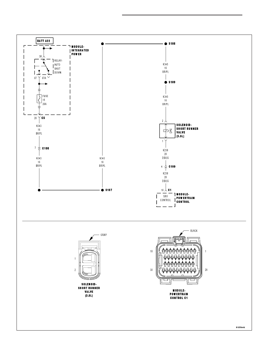
P2008–SHORT RUNNER VALVE SOLENOID CIRCUIT

For a complete wiring diagram Refer to Section 8W.

9 - 700

ENGINE ELECTRICAL DIAGNOSTICS

LX

When Monitored:
With the ignition on. ASD Relay energized. Battery voltage greater than 10 volts.

Set Condition:
The PCM senses the SRV is not at the desired state. One Trip Fault.

Possible Causes

(K343) FUSED AUTO SHUT DOWN RELAY OUTPUT OPEN

(K236) SRV CONTROL CIRCUIT SHORT TO BATTERY VOLTAGE

(K236) SRV CONTROL CIRCUIT SHORT TO GROUND

(K236) SRV CONTROL CIRCUIT OPEN

SHORT RUNNER VALVE SOLENOID

PCM

Always perform the Pre-Diagnostic Troubleshooting procedure before proceeding. (Refer to 9 - ENGINE -
DIAGNOSIS AND TESTING).

Diagnostic Test

1.

ACTIVE DTC

Ignition on, engine not running.

With a scan tool, read DTC.

Is the DTC active at this time?

Yes

>> Go To 2

No

>> Refer to the INTERMITTENT CONDITION Diagnostic Procedure.

Perform the POWERTRAIN VERIFICATION TEST. (Refer to 9 - ENGINE - STANDARD PROCEDURE)

2.

SHORT RUNNER VALVE SOLENOID OPERATION

Turn the ignition off.

Disconnect the SRV Solenoid harness connector.

Ignition on, engine not running.

Using a 12–volt test light, connect one end to the (K236) SRV Control circuit and the other end the (Z904) Ground
circuit in the SRV Solenoid harness connector.

With the scan tool, actuate (Toggle) the SRV Solenoid.

Does the test light illuminate brightly and flash on and off?

Yes

>> Replace the Short Runner Valve Solenoid.

Perform the POWERTRAIN VERIFICATION TEST. (Refer to 9 - ENGINE - STANDARD PROCEDURE)

No

>> Go To 3

LX

ENGINE ELECTRICAL DIAGNOSTICS

9 - 701

3.

(K343) FUSED AUTO SHUT DOWN RELAY OUTPUT2 CIRCUIT OPEN

Turn the ignition off.

Disconnect the Short Runner Valve Solenoid harness connector.

Turn the ignition on.

Using the scan tool, actuate (Toggle) the ASD Relay.

Using a 12-volt test light connected ground, probe the Fused ASD
Relay Output circuit in the SRV Solenoid harness connector.

Does the test light illuminate brightly and flash on and off?

Yes

>> Go To 4

No

>> Repair the (K343) Fused ASD Relay Output circuit.

Perform the POWERTRAIN VERIFICATION TEST. (Refer
to 9 - ENGINE - STANDARD PROCEDURE)

4.

(K236) SRV CONTROL CIRCUIT SHORT TO BATTERY VOLTAGE

Turn the ignition off

Disconnect the PCM harness connectors.

Turn the ignition on.

Measure the voltage of the (K236) SRV Control circuit in the SRV Sole-
noid harness connector.

Does the voltage indicate voltage present?

Yes

>> Repair the short to voltage in the SRV Control circuit.

Perform the POWERTRAIN VERIFICATION TEST. (Refer
to 9 - ENGINE - STANDARD PROCEDURE)

No

>> Go To 5

5.

(K236) SRV CONTROL CIRCUIT SHORT TO GROUND

Turn the ignition off.

Measure the resistance between the (K236) SRV Control circuit in the
SRV Solenoid harness connector and ground.

Is the resistance below 100 ohms?

Yes

>> Repair the short to ground in the (K236) SRV Control cir-

cuit.

Perform the POWERTRAIN VERIFICATION TEST. (Refer
to 9 - ENGINE - STANDARD PROCEDURE)

No

>> Go To 6

9 - 702

ENGINE ELECTRICAL DIAGNOSTICS

LX

6.

(K236) SRV CONTROL CIRCUIT OPEN

CAUTION: Do not probe the PCM harness connectors. Probing the
PCM harness connectors will damage the PCM terminals resulting
in poor terminal to pin connection. Install Miller Special Tool #8815
to perform diagnosis.
Measure the resistance of the (K236) SRV Control circuit between from
the SRV Solenoid harness connector to the appropriate terminal of the
special tool.

Is the resistance below 5.0 ohms?

Yes

>> Go To 7

No

>> Repair the open in the (K236) SRV Control circuit.

Perform the POWERTRAIN VERIFICATION TEST. (Refer
to 9 - ENGINE - STANDARD PROCEDURE)

7.

PCM

NOTE: Before continuing, check the PCM harness connector ter-
minals for corrosion, damage, or terminal push out. Repair as nec-
essary.
Using the schematics as a guide, inspect the wire harness and connec-
tors. Pay particular attention to all Power and Ground circuits.

Were there any problems found?

Yes

>> Repair as necessary.

Perform the POWERTRAIN VERIFICATION TEST. (Refer
to 9 - ENGINE - STANDARD PROCEDURE)

No

>> Replace and program the Powertrain Control Module per Service Information.

Perform the POWERTRAIN VERIFICATION TEST. (Refer to 9 - ENGINE - STANDARD PROCEDURE)

LX

ENGINE ELECTRICAL DIAGNOSTICS

9 - 703


Content   ..  1167  1168  1169  1170   ..