Content .. 1131 1132 1133 1134 ..
Chrysler 300/300 Touring/300C, Dodge Magnum. Manual - part 1133
•
When Monitored:
Ignition on.
•
Set Condition:
If the output of Brake Switch No.1 to the PCM looks like it is not applied, while Brake Switch No.2 circuit is
applied the fault will mature in 60ms. One Trip Fault.
Possible Causes
(B15) BRAKE SWITCH NO.1 SIGNAL SHORTED TO GROUND
(B15) BRAKE SWITCH NO.1 SIGNAL OPEN
(B16) BRAKE SWITCH NO.2 SIGNAL SHORTED TO GROUND
(B16) BRAKE SWITCH NO.2 SIGNAL OPEN
(Z912) GROUND CIRCUIT OPEN
(F202) FUSED IGNITION SWITCH OUTPUT OPEN
STOP LAMP SWITCH
PCM
Always perform the Pre-Diagnostic Troubleshooting procedure before proceeding. (Refer to 9 - ENGINE -
DIAGNOSIS AND TESTING).
Diagnostic Test
1.
ACTIVE DTC
NOTE: Make sure the Stop Lamp Switch is properly adjusted before continuing.
NOTE: Make sure the Stop Lamp Switch is properly wired, such as (B15) Brake Switch No.1 and (B16) Brake
Lamp Switch No.2 circuits are not switched at the harness connector.
Ignition on, engine not running.
With a scan tool, read DTCs.
Is the DTC active at this time?
Yes
>> Go To 2
No
>> Refer to the INTERMITTENT CONDITION Diagnostic Procedure.
Perform the POWERTRAIN VERIFICATION TEST. (Refer to 9 - ENGINE - STANDARD PROCEDURE)
2.
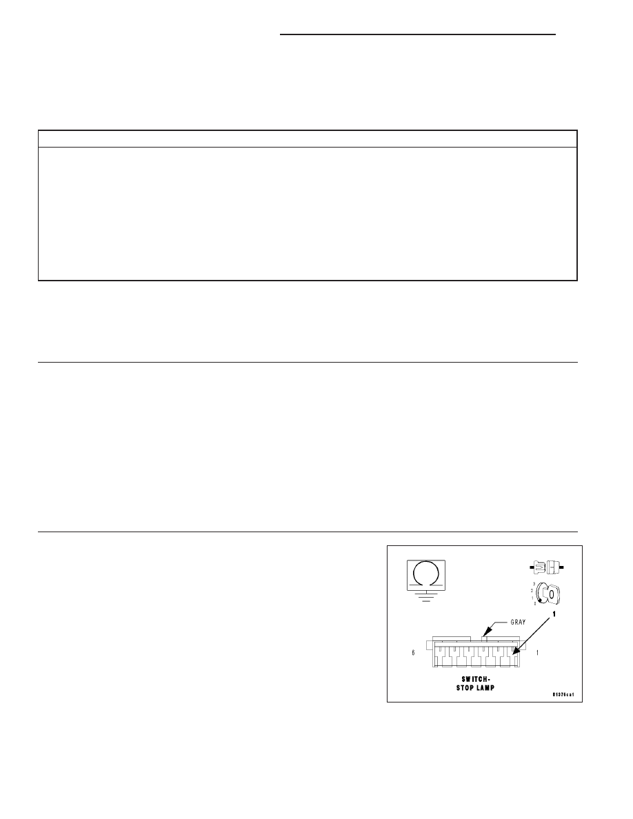
(B15) BRAKE SWITCH NO.1 SIGNAL SHORTED TO GROUND
Turn the ignition off.
Disconnect the Stop Lamp Switch harness connector.
Disconnect the PCM harness connectors.
Measure the resistance between the (B15) Brake Switch No.1 Signal
circuit in the Stop Lamp Switch harness connector and ground.
Is the resistance below 100 ohms?
Yes
>> Repair the short to ground in the (B15) Brake Switch No.1
Signal circuit.
Perform the POWERTRAIN VERIFICATION TEST. (Refer
to 9 - ENGINE - STANDARD PROCEDURE)
No
>> Go To 3
9 - 556
ENGINE ELECTRICAL DIAGNOSTICS
LX