Content .. 1074 1075 1076 1077 ..
Chrysler 300/300 Touring/300C, Dodge Magnum. Manual - part 1076
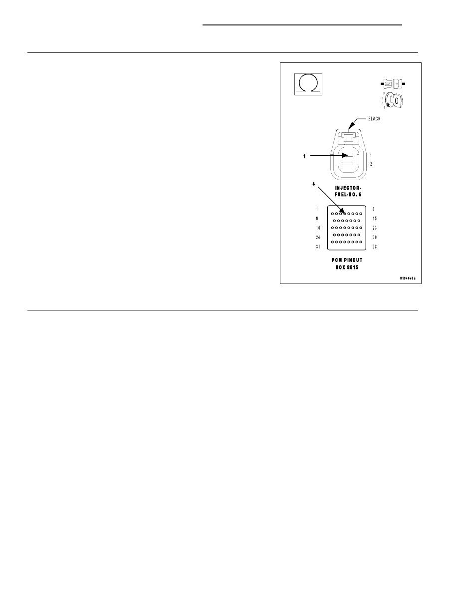
11.
(K58) INJECTOR CONTROL NO.6 CIRCUIT
Turn the ignition off.
Disconnect the PCM harness connectors.
CAUTION: Do not probe the PCM harness connectors. Probing the
PCM harness connectors will damage the PCM terminals resulting
in poor terminal to pin connection. Install Miller Special Tool #8815
to perform diagnosis.
Check the (K58) Injector Control No.6 circuit for an open, short to
ground, and short to voltage.
Was a problem found with the (K58) Injector Control No.6 cir-
cuit?
Yes
>> Repair the excessive resistance or short in the (K58) Injec-
tor Control No.6 circuit.
Perform the POWERTRAIN VERIFICATION TEST. (Refer
to 9 - ENGINE - STANDARD PROCEDURE)
No
>> Go To 17
12.
FUEL SUPPLY LINE RESTRICTED
Turn the ignition off.
WARNING: The fuel system is under a constant pressure (even with the engine off). Before testing or ser-
vicing any fuel system hose, fitting or line, the fuel system pressure must be released. Failure to follow
these instructions can result in personal injury or death.
Raise vehicle on hoist, and disconnect the fuel pressure line at the fuel pump module.
Install special tool #6539 (5/16
9
) #6631(3/8
9
) fuel line adapter and the fuel pressure gauge between the fuel supply
line and the fuel pump module.
Ignition on, engine not running.
With the scan tool, actuate the ASD Fuel System test and observe the fuel pressure gauge.
NOTE: Fuel pressure specification is 407 KPa +/- 34 KPa (59 psi +/- 5 psi).
Is the fuel pressure within specification?
Yes
>> Repair or replace fuel supply line as necessary.
Perform the POWERTRAIN VERIFICATION TEST. (Refer to 9 - ENGINE - STANDARD PROCEDURE)
No
>> Go To 13
9 - 328
ENGINE ELECTRICAL DIAGNOSTICS
LX