Chrysler 300/300 Touring/300C, Dodge Magnum. Manual - part 66


  Index      Chrysler     Chrysler 300/300 Touring/300C, Dodge Magnum - service repair manual


Search            


Content   ..  64  65  66  67   ..


Chrysler 300/300 Touring/300C, Dodge Magnum. Manual - part 66


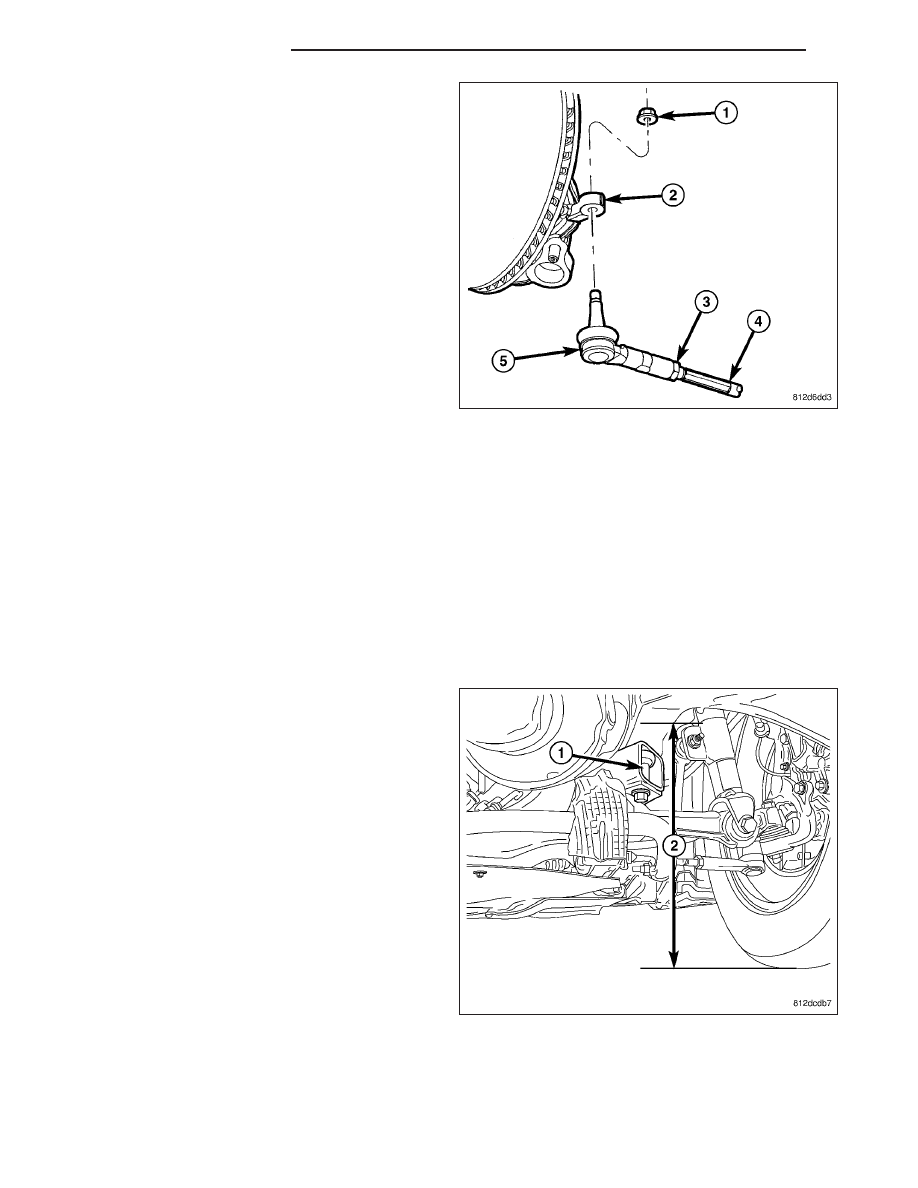
5. RWD – Tighten the tie rod jam nut (3) to 75 N·m

(55 ft. lbs.) torque using care not to lose adjust-
ment.

6. Make sure the inner tie rod-to-steering gear boot is

not twisted, then reinstall the boot clamp at the
inner tie rod.

7. Adjust front toe on opposite side of vehicle using

the above procedure as necessary.

CURB HEIGHT MEASUREMENT

The wheel alignment is to be checked and all alignment adjustments made with the vehicle at its required curb
height specification.

Vehicle height is to be checked with the vehicle on a flat, level surface, preferably a vehicle alignment rack. The
tires are to be inflated to the recommended pressure. All tires are to be the same size as standard equipment.
Vehicle height is checked with the fuel tank full of fuel, and no passenger or luggage compartment load.

Vehicle height is not adjustable. If the measurement is not within specifications, inspect the vehicle for bent or weak
suspension components. Compare the parts tag on the suspect coil spring(s) to the parts book and the vehicle
sales code, checking for a match. Once removed from the vehicle, compare the coil spring height to a correct new
or known good coil spring. The heights should vary if the suspect spring is weak.

NOTE: When measuring, the maximum left-to-right differential is not to exceed 12.5 mm (0.5 in.).

1. Front – On each side of the vehicle, measure the

distance (2) from the frame rail just behind the
engine cradle rear mount (1) to the floor or align-
ment rack/lift runway surface. It may be necessary
to measure to the bottom of a straight edge, placed
from lift runway to runway, to get an accurate
measurement.

2 - 218

WHEEL ALIGNMENT

LX

2. Rear – On each side of the vehicle, measure the

distance (2) from the travel limiter (1) attached to
the front rear crossmember mount bushing to the
floor or alignment rack/lift runway surface. It may
be necessary to measure to the bottom of a
straight edge, placed from lift runway to runway, to
get an accurate measurement.

3. Compare the measurements to the specifications listed in the following Curb Height Specifications chart.

CURB HEIGHT SPECIFICATIONS

MODEL

FRONT

REAR

ALL-WHEEL-DRIVE

352 mm ± 10 mm

13.85 in. ± 0.39 in

308 mm ± 10 mm

12.13 in. ± 0.39 in.

REAR-WHEEL-DRIVE

328 mm ± 10 mm

12.91 in. ± 0.39 in

296 mm ± 10 mm

11.65 in. ± 0.39 in.

SRT8

321 mm ± 12 mm

12.64 in. ± 0.47 in

290 mm ± 12 mm

11.42 in. ± 0.47 in.

POLICE PACKAGE (Without Equipment*)

345 mm ± 10 mm

13.58 in. ± 0.39 in

315 mm ± 10 mm

12.40 in. ± 0.39 in

* NOTE:

Police Package height specifications given are for settled vehicles without additional standard police equipment

added. Once police equipment is added, estimated at 520 lbs. (400 lbs. for Magnum with 5.7L), vehicles should

meet normal REAR-WHEEL-DRIVE specifications as listed above.

SPECIFICATIONS

WHEEL ALIGNMENT

NOTE: All specifications are given in degrees.

NOTE: All wheel alignments are to be set at curb height. (Refer to 2 - SUSPENSION/WHEEL ALIGNMENT -
STANDARD PROCEDURE)

ALL-WHEEL-DRIVE

FRONT WHEEL ALIGNMENT

PREFERRED SETTING

ACCEPTABLE RANGE

CAMBER - LEFT

0.00°

2

0.50° to +0.50°

CAMBER - RIGHT

2

0.30°

2

0.80° to +0.20°

CROSS-CAMBER (Maximum side-to-side
difference)

0.30°

2

0.25° to +1.00°

CASTER - LEFT

+4.50°

+3.50° to +5.50°

LX

WHEEL ALIGNMENT

2 - 219

FRONT WHEEL ALIGNMENT

PREFERRED SETTING

ACCEPTABLE RANGE

CASTER - RIGHT

+5.10°

+4.10° to +6.10°

CROSS-CASTER (Maximum side-to-side
difference)

2

0.60°

2

1.20° to 0.00°

TOE - INDIVIDUAL

0.00°

2

0.05° to +0.05°

TOE - TOTAL**

0.00°

2

0.10° to +0.10°

Maximum side-to-side difference

0.00°

0.06°

REAR WHEEL ALIGNMENT

PREFERRED SETTING

ACCEPTABLE RANGE

CAMBER*

2

0.75°

2

1.25° to

2

0.05°

CROSS-CAMBER (Maximum side-to-side
difference)

0.00°

2

0.80° to +0.80°

TOE - INDIVIDUAL LEFT

+0.17°

+0.02° to +0.32°

TOE - INDIVIDUAL RIGHT

+0.03°

2

0.12° to +0.18°

THRUST ANGLE

+0.07°

2

0.08° to +0.22°

Notes:

* For reference only. These are nonadjustable angles.

** TOTAL TOE is the sum of both left and right wheel toe settings. TOTAL TOE must be equally split between
each wheel on the same axle to ensure the steering wheel is centered after setting toe. Positive toe is toe-in and
negative toe is toe-out

REAR-WHEEL-DRIVE

FRONT WHEEL ALIGNMENT

PREFERRED SETTING

ACCEPTABLE RANGE

CAMBER - LEFT

0.00°

2

0.50° to +0.50°

CAMBER - RIGHT

2

0.30°

2

0.80° to +0.20°

CROSS-CAMBER (Maximum side-to-side
difference)

0.30°

2

0.25° to +1.00°

CASTER - LEFT

+9.40°

+8.40° to +10.40°

CASTER - RIGHT

+10.40°

+9.40° to +11.40°

CROSS-CASTER (Maximum side-to-side
difference)

2

1.00°

2

1.60° to

2

0.40°

TOE - INDIVIDUAL

0.00°

2

0.05° to +0.05°

TOE - TOTAL**

0.00°

2

0.10° to +0.10°

Maximum side-to-side difference

0.00°

0.06°

REAR WHEEL ALIGNMENT

PREFERRED SETTING

ACCEPTABLE RANGE

CAMBER*

2

0.75°

2

1.25° to

2

0.05°

CROSS-CAMBER (Maximum side-to-side
difference)

0.00°

2

0.80° to +0.80°

TOE - INDIVIDUAL LEFT

+0.17°

+0.02° to +0.32°

TOE - INDIVIDUAL RIGHT

+0.03°

2

0.12° to +0.18°

THRUST ANGLE

+0.07°

2

0.08° to +0.22°

Notes:

* For reference only. These are nonadjustable angles.

** TOTAL TOE is the sum of both left and right wheel toe settings. TOTAL TOE must be equally split between
each wheel on the same axle to ensure the steering wheel is centered after setting toe. Positive toe is toe-in and
negative toe is toe-out

2 - 220

WHEEL ALIGNMENT

LX

RIGHT-HAND-DRIVE

FRONT WHEEL ALIGNMENT

PREFERRED SETTING

ACCEPTABLE RANGE

CAMBER - LEFT

2

0.20°

2

0.70° to +0.30°

CAMBER - RIGHT

0.10°

2

0.40° to +0.60°

CROSS-CAMBER (Maximum side-to-side
difference)

2

0.30°

2

1.00° to +0.25°

CASTER - LEFT

+10.30°

+9.30° to +11.30°

CASTER - RIGHT

+9.50°

+8.50° to +10.50°

CROSS-CASTER (Maximum side-to-side
difference)

0.80°

0.20° to 1.40°

TOE - INDIVIDUAL

0.00°

2

0.05° to +0.05°

TOE - TOTAL**

0.00°

2

0.10° to +0.10°

Maximum side-to-side difference

0.00°

0.06°

REAR WHEEL ALIGNMENT

PREFERRED SETTING

ACCEPTABLE RANGE

CAMBER*

2

0.75°

2

1.25° to

2

0.05°

CROSS-CAMBER (Maximum side-to-side
difference)

0.00°

2

0.80° to +0.80°

TOE - INDIVIDUAL LEFT

+0.17°

+0.02° to +0.32°

TOE - INDIVIDUAL RIGHT

+0.03°

2

0.12° to +0.18°

THRUST ANGLE

+0.07°

2

0.08° to +0.22°

Notes:

* For reference only. These are nonadjustable angles.

** TOTAL TOE is the sum of both left and right wheel toe settings. TOTAL TOE must be equally split between
each wheel on the same axle to ensure the steering wheel is centered after setting toe. Positive toe is toe-in and
negative toe is toe-out

LX

WHEEL ALIGNMENT

2 - 221


Content   ..  64  65  66  67   ..