Chrysler 300/300 Touring/300C, Dodge Magnum. Manual - part 65
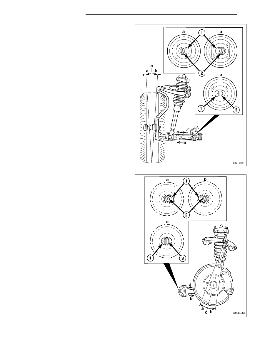
NOTE: The original (non-grooved) mounting bolt
(3) lies through the center of the hole (1), between
the “bat wings” (c).
5. Camber Adjustment – The adjustment bolts are
designed to work in conjunction with “bat wing”
holes that are formed into the inner metal of the
lower control arm bushing (1) allowing for lower
control arm movement approximately 0.3° in either
direction.
•
To achieve more positive camber, refer to (a) in
the figure. Move the control arm or tension strut
in the desired direction, then insert the adjust-
ment bolt (2) with a washer installed through the
round hole in the engine cradle and bat wing
hole (1) in the bushing inner metal.
•
To achieve more negative camber, refer to (b) in
the figure. Move the control arm or tension strut
in the desired direction, then insert the adjust-
ment bolt (2) with a washer installed through the
round hole in the engine cradle and bat wing
hole (1) in the bushing inner metal.
NOTE: The original (non-grooved) mounting bolt
(3) lies through the center of the hole (1), between
the “bat wings” (c).
6. Caster Adjustment – The adjustment bolts are
designed to work in conjunction with “bat wings”
that are formed into the engine cradle (1) allowing
for tension strut movement approximately 0.3° in
either direction.
•
To achieve more positive caster, refer to (a) in
the figure. Move the tension strut in the desired
direction, then insert the adjustment bolt (2) with
a washer installed through the bat wing hole in
the engine cradle (1) and the round hole in the
bushing inner metal.
•
To achieve more negative caster, refer to (b) in
the figure. Move the tension strut in the desired
direction, then insert the adjustment bolt (2) with
a washer installed through the bat wing hole in
the engine cradle (1) and the round hole in the
bushing inner metal.
7. Start a NEW nut and a washer (on RWD vehicles) on the end of the mounting bolt by hand, then while holding
the head of the bolt stationary, install the nut. Do not tighten the nut at this time.
2 - 214
WHEEL ALIGNMENT
LX