Chrysler 300/300 Touring/300C, Dodge Magnum. Manual - part 44


  Index      Chrysler     Chrysler 300/300 Touring/300C, Dodge Magnum - service repair manual


Search            


Content   ..  42  43  44  45   ..


Chrysler 300/300 Touring/300C, Dodge Magnum. Manual - part 44


COMPRESSION LINK

REMOVAL

1. Raise and support vehicle. (Refer to LUBRICATION & MAINTENANCE/HOISTING - STANDARD PROCEDURE)

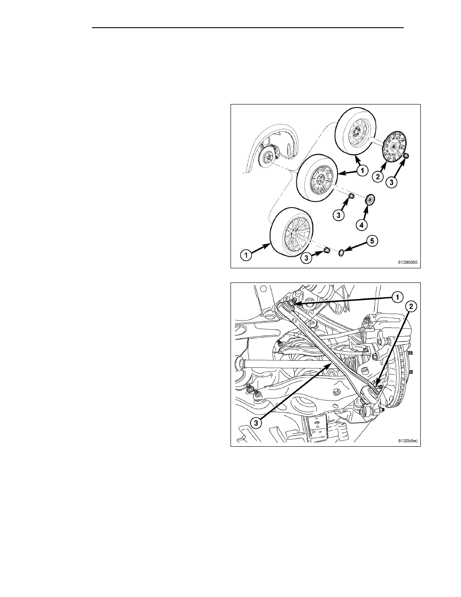
2. Remove wheel mounting nuts (3), then rear tire

and wheel assembly (1).

3. Remove bolt and nut (2) mounting link (3) at

knuckle.

4. Remove bolt and nut (1) mounting link (3) at cross-

member.

5. Remove link (3).

INSTALLATION

NOTE: Although the compression link is different end-to-end, there is no top and bottom.

2 - 130

REAR

LX

1. Position link and install bolt and nut (1) mounting

link (3) at crossmember. Do not tighten bolt at
this time.

2. Install bolt and nut (2) mounting link (3) at knuckle.

Do not tighten bolt at this time.

3. Install tire and wheel assembly (1). Tighten wheel

mounting nuts (3) to 150 N·m (110 ft. lbs.) torque.
(Refer to 22 - TIRES/WHEELS - INSTALLATION)

4. Lower vehicle.

5. Position vehicle on alignment rack/drive-on lift.

Raise vehicle as necessary to access link fasten-
ers.

6. Tighten compression link fasteners to:

Bolt at crossmember – 85 N·m (63 ft. lbs.)
torque.

Bolt at knuckle – 81 N·m (60 ft. lbs.) torque.

7. Perform wheel alignment. (Refer to 2 - SUSPEN-

SION/WHEEL

ALIGNMENT

-

STANDARD

PROCEDURE)

LX

REAR

2 - 131

SPRING LINK

REMOVAL

SPRING LINK

1. Raise and support vehicle. (Refer to LUBRICATION & MAINTENANCE/HOISTING - STANDARD PROCEDURE)

2. Access and remove rear spring. (Refer to 2 - SUSPENSION/REAR/SPRING - REMOVAL)

3. Export Only – If servicing right spring link, discon-

nect headlamp leveling sensor (1) link at spring link
(3).

4. Remove spring link-to-knuckle nut and bolt (2).

2 - 132

REAR

LX

CAUTION: It important to use Guide (2), Special
Tool 9361-2, when tapping sleeve in knuckle to
help keep Tap (1) , Special Tool 9361-1, straight
during use or damage to Tap may occur.

5. Place Guide 9361-2 (2) against sleeve (3) in

knuckle to keep Tap 9361-1 (1) straight. Using Tap
with an appropriate handle, cut threads approxi-
mately halfway through bushing (or about six com-
plete threads). It is important to back tap out,
clean out burrs and lubricate Tap often during
process.

NOTE: Prior to using Special Tool 9361, lubricate
Bolt (1) threads to provide ease of use and pro-
mote tool longevity.

6. Assemble Remover, Special Tool 9361, as shown.

(1) Bolt 9361-3

(2) Nut

(3) Spherical Washer

(4) Thrust Bearing

(5) Sleeve 9361-4 (RWD)

(5) Sleeve 9361-5 (AWD – Left Side)

(5) Sleeve 9361-6 (AWD – Right Side)

NOTE: When installing thrust bearing on Remover,
be sure to place hardened side against nut. Place
bearing outer cage against stationary component.

NOTE: It is important to use appropriate Sleeve on
Remover to provide proper Tool-to-Knuckle contact. RWD sleeve can be used on either side while AWD
knuckles require specific left or right side Sleeves.

LX

REAR

2 - 133


Content   ..  42  43  44  45   ..