Chrysler 300/300 Touring/300C, Dodge Magnum. Manual - part 26


  Index      Chrysler     Chrysler 300/300 Touring/300C, Dodge Magnum - service repair manual


Search            


Content   ..  24  25  26  27   ..


Chrysler 300/300 Touring/300C, Dodge Magnum. Manual - part 26


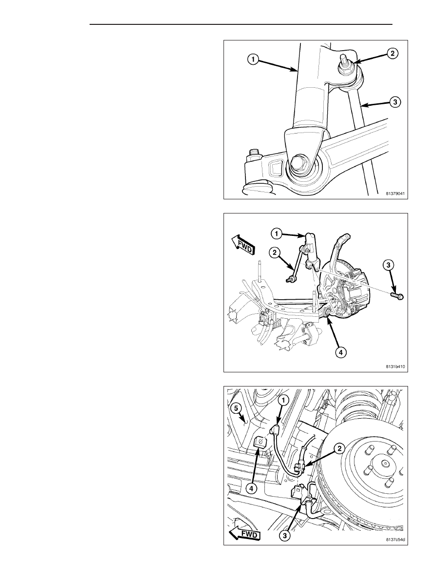
5. Remove nut (2) fastening stabilizer link (3) to shock

assembly (1). Slide link ball joint stem from shock
assembly.

6. Remove bolt (3) securing shock assembly (1) to

lower control arm (4).

7. Disconnect wheel speed sensor cable routing clip

(2) at brake tube bracket (3).

2 - 58

FRONT

LX

8. Loosen nut (4) attaching upper ball joint stud (1) to

knuckle. Back nut off until nut is even with end of
stud. Keeping nut on at this location will help
keep end of stud from distorting while using
Puller in next step.

CAUTION: In following step, use care not to dam-
age ball joint seal boot while sliding Puller, Special
Tool 9360, into place past seal boot.

9. Using Puller (2), Special Tool 9360, separate upper

ball joint stud (1) from knuckle.

10. Remove nut (4) from end of upper ball joint stud

(1).

11. Tip top of knuckle outward using care not to over-

extend bake flex hose.

12. Remove shock assembly from vehicle.

LX

FRONT

2 - 59

DISASSEMBLY

The shock assembly must be removed from vehicle for it to be disassembled and assembled.

For shock assembly disassembly and assembly, use of shock Spring Compressor, Pentastar Service Equipment
(PSE) tool W-7200, or equivalent, is recommended to compress coil spring. Follow manufacturer’s instructions
closely.

WARNING: Do not remove shock shaft nut before coil spring is compressed. Coil spring is held under pres-
sure and must be compressed, removing spring tension from upper and lower mounts, before shock
removal.

1. Position shock assembly coil spring (1) on hooks

(2) of Compressor following manufacturers instruc-
tions. Install clamp securing shock to lower spring
coil.

2. Position Compressor upper hooks (1) on upper coil

spring (2) following manufacturers instructions. To
ease installation, rotate shock as necessary posi-
tioning shock in compressor so that upper spring
coil ends (step in upper mount) at straight outward
position from Compressor.

3. Compress coil spring until all spring tension is

removed from upper mount.

2 - 60

FRONT

LX

4. Position Wrench (2), Special Tool 9362, on shock

shaft retaining nut. Next, insert 8 mm socket
though Wrench onto hex located on end of shock
shaft. While holding shock shaft from turning,
remove nut from shock shaft using Wrench.

5. Remove clamp from bottom of coil spring and

remove shock and lower isolator out through bot-
tom of coil spring.

NOTE: If upper mount or coil spring needs to be serviced, proceed with next step, otherwise, proceed with
step 8.

6. Remove upper mount (1) from shock shaft and coil

spring.

NOTE: Prior to removing spring from compressor,
note location of lower spring coil end in relation-
ship to compressor to ease assembly of compo-
nents later.

7. Back off Compressor drive, releasing tension from

coil spring. Push back compressor upper hooks
and remove coil spring from Compressor.

LX

FRONT

2 - 61


Content   ..  24  25  26  27   ..