Chrysler Town & Country/Voyager, Dodge Caravan, Plymouth Voyager. Manual - part 314


  Index      Chrysler     Chrysler Town & Country/Voyager, Dodge Caravan, Plymouth Voyager - service repair manual 1992 year


Search            


Content   ..  312  313  314  315   ..


Chrysler Town & Country/Voyager, Dodge Caravan, Plymouth Voyager. Manual - part 314


REMOVAL

(1) Drain cooling system refer to Cooling System

Group 7 for procedure and disconnect negative battery
cable.

Remove intake manifold, and throttle body. Refer to

Group 11 Exhaust System and Intake Manifold.

(2) Disconnect coil wires, sending unit wire, heater

hoses and by-pass hose.

(3) Remove closed ventilation system, evaporation

control system and cylinder head covers.

(4) Remove exhaust manifolds.
(5) Remove rocker arm and shaft assemblies. Re-

move push rods and identify to insure installation
in original locations.

(6) Remove the 9 head bolts from each cylinder head

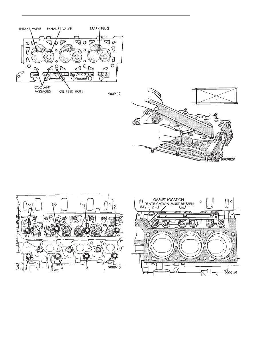
and remove cylinder heads (Fig. 7).

INSPECTION

(1) Before cleaning, check for leaks, damage and

cracks.

(2) Clean cylinder head and oil passages.
(3) Check cylinder head for flatness (Fig. 8).
(4) Inspect all surfaces with a straightedge if there is

any reason to suspect leakage. If out of flatness exceeds
.019mm (.00075 inch). times the span length in inches

in any direction, either replace head or lightly machine
the head surface. As an example, if a 12 inch span is
1mm (.004 inch) out of flat, allowable is 12 x .019mm
(.00075 inch) equals .22mm (.009 in.) This amount of
out of flat is acceptable.

*Maximum of 0.2 mm (.008 inch) for grinding is

permitted.

CAUTION: This is a combined total dimension of
stock removal from cylinder head and block top
surface.

INSTALLATION

(1) Clean all surfaces of cylinder block and cylinder

heads.

(2) Install new gaskets on cylinder block (Fig. 9).

The Cylinder head bolts are torqued using the

torque yield method, they should be examined
BEFORE reuse. If the threads are necked down,
the bolts should be replaced 
(Fig. 10).

Necking can be checked by holding a scale or straight

edge against the threads. If all the threads do not
contact the scale the bolt should be replaced.

Fig. 6 Cylinder Head Assembly

Fig. 7 Cylinder Head Bolts Location

Fig. 8 Check Cylinder Head

Fig. 9 Head Gasket Installation

.

3.3L ENGINE

9 - 87

(3) Tighten the cylinder head bolts 1 thru 8 in the

sequence shown in (Fig. 11). Using the 4 step torque
turn method, tighten according to the following values:
• First-All to 61 NIm (45 ft. lbs.)

• Second-All to 88 NIm (65 ft. lbs.)

• Third-All (again) to 88 NIm (65 ft. lbs.)

• Fourth + 1/4 Turn Do not use a torque wrench
for this step

(4) Bolt torque after 1/4 turn should be over 122

N

Im(90 ft. lbs.). If not, replace the bolt.

(5) Tighten head bolt number 9 (Fig. 11) to 33 N

Im

(25 ft. lbs.) after head bolts 1 thru 8 have been tighten
to specifications.

(6) Inspect push rods and replace worn or bent rods.
(7) Install push rods, rocker arm and shaft assem-

blies with the stamped steel retainers in the four
positions, tighten to 28 N

Im (250 in. lbs.) (Fig. 12).

(8) Place new cylinder head cover gaskets in position

and install cylinder head covers. Tighten to 12 N

Im

(105 in. lbs.).

INTAKE MANIFOLD SEALING

The intake manifold gasket is a one-piece stamped

steel gasket with a sealer applied from the manufac-
turer. This gasket has end seals incorporated with it.

WARNING: INTAKE MANIFOLD GASKET IS

MADE OF VERY THIN METAL AND MAY CAUSE
PERSONAL INJURY, HANDLE WITH CARE.

(1) Clean all surfaces of cylinder block and cylinder

heads.

(2) Place a drop ( about 1/4 in. diameter) of Mopar

Silicone Rubber Adhesive Sealant or equivalent, onto
each of the four manifold to cylinder head gasket
corners (Fig. 13).

(3) Carefully install the intake manifold gasket (Fig.

14). Torque end seal retainer screws to 12 N

Im (105 in.

lbs.).

(4) Install intake manifold and (8) bolts and torque

to 1 N

Im (10 in. lbs.). Then retorque bolts to 22 NIm

(200 in. lbs.) in sequence shown in (Fig. 15). Then
retorque again to 22 N

Im (200 in. lbs.). After intake

manifold is in place, inspect to make sure seals are
in place. 
Refer to Group 11 Exhaust System and
Intake Manifold to complete Intake Manifold Assem-
bly.

(5) Install exhaust manifolds and tighten bolts to 27

N

Im (20 ft. lb.) and nuts to 20 NIm (15 ft. lbs.).

(6) Adjust spark plugs to specification in Electrical

Section, Group 8, and install the plugs.

Fig. 10 Checking Bolts for Stretching (Necking)

Fig. 11 Cylinder Head Tightening Sequence

Fig. 12 Rocker Arm Shaft Retainers

Fig. 13 Intake Manifold Gasket Sealing

9 - 88

3.3L ENGINE

.

VALVE SERVICE

VALVES AND VALVE SPRINGS

The valves are arranged in line in the cylinder heads

and inclined 18 degrees. The rocker shaft support and
the valve guides are cast integral with the heads.

REMOVAL

(1) With cylinder head removed, compress valve

springs using Valve Spring Compressor Tool C-3422-B
with adapter 6412 as shown in (Fig. 16).

(2) Remove valve retaining locks, valve spring re-

tainers, valve stem cup seals and valve springs.

(3) Before removing valves,remove any burrs

from valve stem lock grooves to prevent damage
to the valve guides. 
Identify valves to insure instal-
lation in original location.

VALVE INSPECTION

(1) Clean valves thoroughly and discard burned,

warped and cracked valves.

(2) Measure valve stems for wear. Refer to specifica-

tions (Fig. 19).

Valve stems are chrome plated and should not

be polished.

(3) Remove carbon and varnish deposits from inside

of valve guides with a reliable guide cleaner.

(4) Measure valve stem guide clearance as follows:

(a) Install valve into cylinder head so it is 14mm

(.551 inch) off the valve seat. A small piece of hose
may be used to hold valve in place.

(b) Attach dial indicator Tool C-3339 to cylinder

head and set it at right angle of valve stem being
measured (Fig. 17).

(c) Move valve to and from the indicator. Refer to

specifications (Fig. 19).
Ream the guides for valves with oversized stems if

dial indicator reading is excessive or if the stems are
scuffed or scored.

(5) Service valves with oversize stems and over size

seals are available in 0.15mm (.005 inch), 0.40mm,
(.015 inch) and 0.80mm (.030 inch) oversize.

Fig. 14 Intake Manifold Gasket Retainers

Fig. 15 Intake Manifold Removal and Installation

Fig. 16 Compress Valve Springs with Special Tool

C-3422B with adapter 6412

Fig. 17 Measuring Valve Guide Wear

.

3.3L ENGINE

9 - 89

Oversize seals must be used with oversize

valves.

Reamers to accommodate the oversize valve stem are

as follows:

(6) Slowly turn reamer by hand and clean guide

thoroughly before installing new valve. Do not at-
tempt to ream the valve guides from standard
directly to 0.80mm (.030 inch) Use step procedure
of 0.15mm (.005 inch), 0.40mm (.015 inch) and
0.80mm (.030 inch) so the valve guides may be
reamed true in relation to the valve seat. After
reaming guides, the seat runout should be mea-
sured and resurfaced if necessary. See Refacing
Valves and Valve Seats.

VALVE GUIDES

Replace cylinder head if guide does not clean

up with 0.80mm (.030 inch) oversize reamer, or if
guide is loose in cylinder head.

REFACING VALVES AND VALVE SEATS

The intake and exhaust valves have a 44-1/2 to 45

degree face angle. The valve seats have a 45 to 45-1/2
degree face angle. The valve face and valve seat angles
are shown in (Fig. 21).

VALVES

(1) Inspect the remaining margin after the valves

are refaced Refer to specifications (Fig. 20).

VALVE SEATS

CAUTION: Do not un-shroud valves during valve seat
refacing (Fig. 22).

(1) When refacing valve seats, it is important that

the correct size valve guide pilot be used for reseating
stones. A true and complete surface must be obtained.

(2) Measure the concentricity of valve seat using dial

indicator. Total runout should not exceed .051mm (.002
inch) total indicator reading.

(3) Inspect the valve seat with Prussian blue to

determine where the valve contacts the seat. To do this,
coat valve seat LIGHTLY with Prussian blue then set
valve in place. Rotate the valve with light pressure. If
the blue is transferred to the center of valve face,
contact is satisfactory. If the blue is transferred to top
edge of valve face,lower valve seat with

Fig. 18 Intake and Exhaust Valves

Fig. 19 Valve Guide Specifications

Fig. 20 Valve Dimensions

Fig. 21 Valve Seats

9 - 90

3.3L ENGINE

.


Content   ..  312  313  314  315   ..