Chrysler Town & Country/Voyager, Dodge Caravan, Plymouth Voyager. Manual - part 310


  Index      Chrysler     Chrysler Town & Country/Voyager, Dodge Caravan, Plymouth Voyager - service repair manual 1992 year


Search            


Content   ..  308  309  310  311   ..


Chrysler Town & Country/Voyager, Dodge Caravan, Plymouth Voyager. Manual - part 310


PLASTIGAGE MEASUREMENT

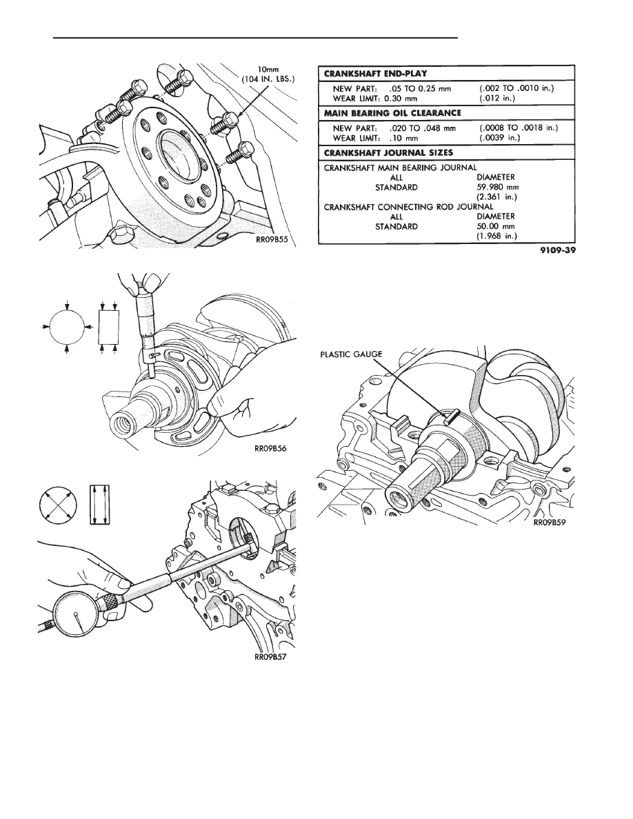
(1) Remove oil from journal and bearing shell.
(2) Install crankshaft.
(3) Cut plastigage to same length as width of the

bearing and place it in parallel with the journal axis.
(Fig. 7).

(4) Install the main bearing cap carefully and

tighten the bolts to specified torque.

CAUTION: Do not rotate crankshaft or the plastigage
will be smeared.

(5) Carefully remove the bearing cap and measure

the width of the plastigage at the widest part using the
scale on the plastigage package (Fig. 8). Refer to
specification (Fig. 6) for proper clearances. Also see
Measuring Main and Connecting Rod Bearing Clear-
ance in Standard Service Procedures.

CRANKSHAFT BEARINGS

INSTALLATION

(1) Install upper main bearing shells making certain

oil holes are in alignment, and bearing tabs seat in
block tabs. All upper bearings have oil grooves (Fig. 9).

THRUST BEARINGS. Crankshaft thrust bearings

(washers) are installed at journal #3 separately from
the radial bearings. Thrust bearings shown in (Fig. 9)
are

different,

one

has

end

positioning

tabs,

Fig. 3 Rear Seal Assembly

Fig. 4 Measure Crankshaft Journal O.D.

Fig. 5 Measure Main Bearing I.D.

Fig. 6 Crankshaft Clearance Specification

Fig. 7 Measure Oil Clearance with Plastigage

.

3.0L ENGINE

9 - 71

while the other is plain. One pair of each thrust
washers are installed into the block and one pair into
the main bearing cap (Fig. 9).

(2) Apply a thin film of grease to plain side of thrust

washers and position them on each side of number
three main bearing. Grooved surface towards crank-
shaft.

(3) Oil the bearings and journals and install crank-

shaft.

(4) Install lower main bearing shells without oil

grooves in monoblock cap.

(5) Install one pair of thrust washers in cap. Refer to

Thrust Bearings (Fig. 9).

(6) Carefully install bearing cap with arrows (Fig.

10) toward timing belt end.

(7) Oil the bearing cap bolt threads, install and

tighten bolts progressively in sequence shown in (Fig.
9) to 80 N

Im (60 ft. lbs.) torque.

CHECKING CRANKSHAFT END PLAY

(1) Mount a dial indicator to front of engine, locating

probe on nose of crankshaft (Fig. 11).

(2) Move crankshaft all the way to the rear of its

travel. (3) Zero the dial indicator.

(4) Move crankshaft all the way to the front and read

the dial indicator. Refer to (Fig. 6) for specification.

CRANKSHAFT OIL SEALS SERVICE

REAR CRANKSHAFT SEAL RETAINER

(1) Install rear crankshaft oil seal in housing with

Special Tool MD998718 (Fig. 12).

(2) Apply (Mopar Silicone Rubber Adhesive Sealant

or equivalent) to oil seal housing (Fig. 13) per proce-
dure detailed in form-in-place gasket section in Stan-
dard Service Procedures.

(3) Apply light coating of engine oil to the entire

circumference of oil seal lip.

Fig. 9 Install Main Bearings

Fig. 8 Measuring Clearance

9 - 72

3.0L ENGINE

.

(4) Install seal assembly on cylinder block and

tighten bolts to 12 N

Im (104 in. lbs.).

FRONT CRANKSHAFT OIL PUMP AND OIL
SEAL

(1) Install oil pump gasket and oil pump case (Figs.

1 and 14).

CAUTION: Install bolts, depending on length in loca-
tions shown in (Fig. 14).

(2) Using front crankshaft oil seal installer Special

Tool MB998306 install oil seal in oil pump (Fig. 15).

CYLINDER BLOCK

Inspect cylinder block for scratches, cracks and rust

or corrosion, and repair or replace as required.

(1) Clean cylinder block and check top surface for

distortion with a straight edge and thickness gauge
(Fig. 16).

(2) Top surface must be flat within:

• Standard Value: 0.05 mm (.002 inch)

Fig. 10 Crankshaft Main Bearing Cap

Fig. 11 Checking Crankshaft End Play

Fig. 12 Install Crankshaft Rear Oil Seal

.

3.0L ENGINE

9 - 73

• Service Limit 0.1 mm (.003 inch)

CAUTION: Maximum of 0.2mm (.008 inch) is permit-
ted. This is a combined total dimension of stock
removal from cylinder head (if any) and block top
surface.

BORING CYLINDER

Examine cylinder walls for scuffs, scoring and mea-

sure cylinder bore for out-of-round or taper. If defec-
tive, bore cylinder to oversize. Measure at points shown
in (Fig. 17).

Four oversize pistons are available (0.25mm (.010

inch) 0.50mm (.020 inch) 0.75mm (.030 inch) and
1.0mm (.039 inch). Determine oversize piston on basis
of largest cylinder bore.

(1) Bore to specified clearance between the piston

O.D. and cylinder. The measuring point of the piston
O.D. is shown in (Fig. 18).

(2) Based on measured piston O.D., calculate boring

finish dimension. Boring finish dimension equals pis-
ton O.D. plus 0.03 to 0.05 mm (.0012 to .002 inch)
(clearance between piston O.D. and cylinder) minus
0.02 mm which is the boring margin.

Fig. 13 Apply Sealant to Oil Seal Housing

Fig. 14 Oil Pump

Fig. 15 Crankshaft Front Oil Seal

Fig. 16 Distortion Check

Fig. 17 Measure Cylinder Bore

9 - 74

3.0L ENGINE

.


Content   ..  308  309  310  311   ..