Chrysler Town & Country/Voyager, Dodge Caravan, Plymouth Voyager. Manual - part 205


  Index      Chrysler     Chrysler Town & Country/Voyager, Dodge Caravan, Plymouth Voyager - service repair manual 1992 year


Search            


Content   ..  203  204  205  206   ..


Chrysler Town & Country/Voyager, Dodge Caravan, Plymouth Voyager. Manual - part 205


input sent to the engine controller. The engine control-
ler interprets the camshaft sensor input (along with
the crankshaft sensor input) to determine crankshaft
position. The engine controller uses crankshaft posi-
tion reference to determine injector sequence and igni-
tion timing.

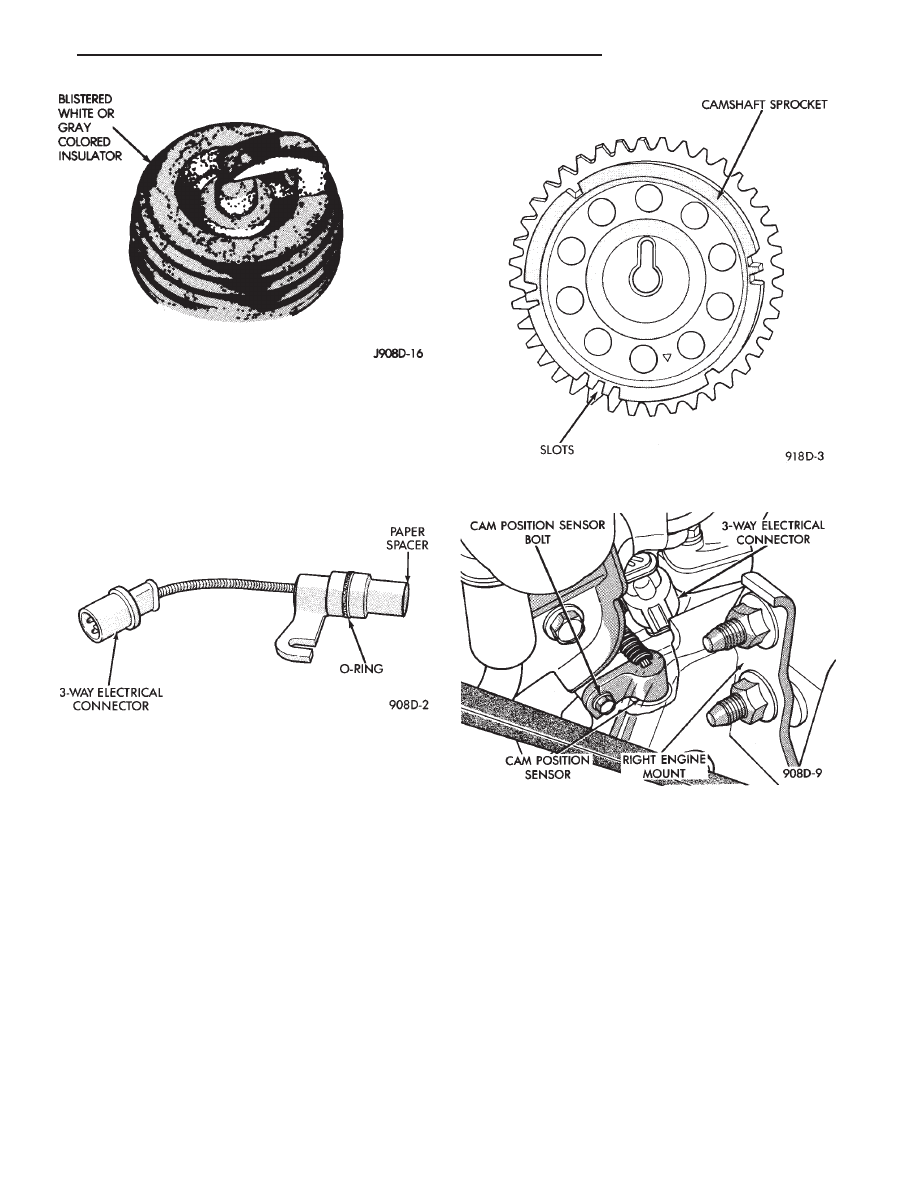
The camshaft sensor determines when a slot in the

camshaft gear passes beneath it (Fig. 14). When a slot
is sensed, the input voltage from the sensor to the
engine controller switches from low (less than 0.3 volts)
to high (5 volts). As the slot or window passes, the input
voltage is switched back to low (less than 0.3 volts).

The camshaft sensor is mounted to the top of the

timing case cover (Fig. 15). The bottom of the sensor is
positioned above the camshaft sprocket. The distance
between the bottom of sensor and the camshaft
sprocket is critical to the operation of the sys-
tem. When servicing the camshaft sensor, refer to
the 3.3L Ignition System—Service Procedures
section in this Group.

CRANKSHAFT TIMING SENSOR

The crankshaft sensor (Fig. 16) senses slots cut into

the transmission driveplate extension. There are a 3
sets of slots. Each set contains 4 slots, for a total of 12
slots (Fig. 17). Basic timing is set by the position of the
last slot in each group. Once the engine controller

senses the last slot, it determines crankshaft position
(which piston will next be at TDC) from the camshaft
sensor input. It may take the controller up to two
thirds of an engine revolution to determine crankshaft
position.

The engine controller uses crankshaft position refer-

ence to determine injector sequence and ignition tim-
ing. Once crankshaft position has been determined, the
engine controller begins energizing the injectors in
sequence.

The crankshaft sensor is located in the transmission

housing, above the vehicle distance sensor (Fig. 18).
The bottom of the sensor is positioned next to the drive
plate. The distance between the bottom of sensor
and the drive plate is critical to the op-

Fig. 12 Spark Plug Overheating

Fig. 13 Camshaft Sensor

Fig. 14 Camshaft Gear

Fig. 15 Camshaft Sensor Location

.

IGNITION SYSTEMS

8D - 29

eration of the system. When servicing the crank-
shaft sensor, refer to the 3.3L Ignition System—
Service Procedures section in this Group.

IGNITION COIL

WARNING: THE 3.3L ENGINE’S DIRECT IGNITION
SYSTEM

GENERATES

APPROXIMATELY

40,000

VOLTS. PERSONAL INJURY COULD RESULT FROM
CONTACT WITH THIS SYSTEM.

The coil assembly consists of 3 coils molded together

(Fig. 19). The coil assembly is mounted on the intake
manifold. High tension leads route to each cylinder
from the coil. The coil fires two spark plugs every
power stroke. One plug is the cylinder under compres-
sion, the other cylinder fires on the exhaust stroke. The
engine controller determines which of the coils to
charge and fire at the correct time.

Coils one fires cylinders 1 and 4, coil two fires

cylinders 2 and 5, coil three fires cylinders three and
six.

The coil’s low primary resistance (0.5-0.7 ohm) allows

the engine controller to fully charge the coil for each
firing.

COOLANT TEMPERATURE SENSOR—ENGINE CON-
TROLLER INPUT

The coolant temperature sensor is located next to the

thermostat housing (Fig. 20). The sensor provides an
input voltage to the engine controller. The sensor is a
variable resistance (thermistor) with a range of -40°F
to 265°F. As coolant temperature varies, the sensors
resistance changes, resulting in a different input volt-
age to the engine controller.

Fig. 16 Crankshaft Sensor

Fig. 17 Timing Slots in Transmission Driveplate

Fig. 18 Crankshaft Sensor Location

Fig. 19 Coil Pack—3.3L Engine

Fig. 20 Coolant Temperature Sensor

8D - 30

IGNITION SYSTEMS

.

The engine controller contains different spark ad-

vance schedules for cold and warm engine operation.
The schedules reduce engine emission and improve
driveability.

When the engine is cold, the engine controller will

demand slightly richer air-fuel mixtures and higher
idle speeds until normal operating temperatures are
reached.

The coolant sensor input is also used for cooling fan

control.

MANIFOLD ABSOLUTE PRESSURE (MAP) SENSOR

The MAP sensor reacts to absolute pressure in the

intake manifold and provides an input voltage to the
engine controller. As engine load changes, manifold
pressure varies. The changes in engine load cause the
MAP sensors resistance to change. The change in MAP
sensor resistance results in a different input voltage to
the engine controller.

The input voltage level supplies the engine controller

with information relating to ambient barometric pres-
sure during engine start-up (cranking) and engine load
while its operating. The engine controller uses this
input along with inputs from other sensors to adjust
air-fuel mixture.

The MAP sensor (Fig. 21) is mounted to the side of

the intake manifold, below the positive crankcase ven-
tilation (PCV) valve. The sensor is connected to the
engine controller electrically.

AUTO SHUTDOWN (ASD) RELAY—ENGINE CON-
TROLLER OUTPUT

The Auto Shutdown Relay (ASD) connects battery

voltage to the fuel injectors and ignition coil. The
ground circuit for the ASD relay is controlled by the
engine controller. The engine controller operates the
relay by switching the ground circuit on and off.

If the engine controller does not receive an ignition

signal input when the ignition key in the RUN posi-
tion, it de-energizes the ASD relay. When the relay is
de-energized the battery voltage is removed from fuel
injectors and ignition coil.

The ASD relay is located on the drivers side fender

well, near to the engine controller (Fig. 22).

Fig. 21 Map Sensor

Fig. 22 Auto Shutdown Relay

.

IGNITION SYSTEMS

8D - 31

3.3L IGNITION SYSTEM—DIAGNOSTIC PROCEDURES

INDEX

page

page

Check Coil Test—3.3L Engine

. . . . . . . . . . . . . . . 32

Coolant Temperature Sensor Test

. . . . . . . . . . . . . 33

Crankshaft Sensor and Camshaft Sensor Tests

. . . 34

Failure to Start Test

. . . . . . . . . . . . . . . . . . . . . . . 33

Manifold Absolute Pressure (MAP) Sensor Test

. . . 34

Testing for Spark at Coil

. . . . . . . . . . . . . . . . . . . . 32

TESTING FOR SPARK AT COIL

WARNING: THE 3.3L ENGINE DIRECT IGNITION SYS-
TEM GENERATES APPROXIMATELY 40,000 VOLTS.
PERSONAL INJURY COULD RESULT FROM CON-
TACT WITH THIS SYSTEM.

The coil pack contains 3 independent coils. Each coil

must be checked individually.

CAUTION: Spark plug wire damage may occur if the
spark plug is moved more than 1/4 inch away from the
engine ground.

Remove the cable from number 2 spark plug. Insert a

clean spark plug into the spark plug boot, and ground
plug to the engine (Fig. 1).

Crank the engine and look for spark across the

electrodes of the spark plug. Repeat the above test for
the five remaining cylinders. If there is no spark
during all cylinder tests, proceed to the failure to start
test.

If one or more tests indicate irregular, weak, or no

spark, proceed to Check Coil Test.

CHECK COIL TEST—3.3L ENGINE

Coils one fires cylinders 1 and 4, coil two fires

cylinders 2 and 5, coil three fires cylinders three
and six.

Each coil tower is labeled with the number of the

corresponding cylinder.

(1) Remove the ignition cables and measure the

resistance of the cables. Resistance must be between
3,000 to 12,000 ohms per foot of cable. Replace any
cable not within tolerance.

(2) Disconnect the electrical connector from the coil

pack (Fig. 2).

(3) Measure the primary resistance of each coil. At

the coil, connect an ohmmeter between the B+ pin and
the pin corresponding to the cylinders in question (Fig.
3). Resistance on the primary side of each coil should be
0.5-0.7 ohm. Replace the coil if resistance is not within
tolerance.

(4) Remove ignition cables from the secondary tow-

ers of the coil. Measure the secondary resistance of

Fig. 1 Testing For Spark

Fig. 2 Ignition Coil Electrical Connection

Fig. 3 Ignition Coil Terminal Identification

8D - 32

IGNITION SYSTEMS

.


Content   ..  203  204  205  206   ..