Chrysler Town & Country/Voyager, Dodge Caravan, Plymouth Voyager. Manual - part 202


  Index      Chrysler     Chrysler Town & Country/Voyager, Dodge Caravan, Plymouth Voyager - service repair manual 1992 year


Search            


Content   ..  200  201  202  203   ..


Chrysler Town & Country/Voyager, Dodge Caravan, Plymouth Voyager. Manual - part 202


(f) Install throttle body on manifold.
(g) Repeat steps 1 through 14. If the minimum air

flow is still not within specifications, the problem is
not caused by the throttle body.
(16) Shut off engine.
(17) Remove Air Metering Fitting #6457 from the

intake manifold idle purge hose. Reconnect the hose to
the engine vacuum harness tee.

(18) Remove the plug from the PCV valve. Reconnect

the PCV valve hose to the PCV valve.

(19) Disconnect the DRB II.

IGNITION TIMING PROCEDURE—2.5L TBI AND
3.0L ENGINES

WARNING: BE SURE TO APPLY PARKING BRAKE
AND/OR BLOCK WHEELS BEFORE PERFORMING
SETTING IGNITION TIMING OR PERFORMING ANY
TEST ON AN OPERATING ENGINE.

Proper ignition timing is required to obtain optimum

engine performance. The distributor must be correctly
indexed to provide correct initial ignition timing.

(1) Set the gearshift selector in park or neutral and

apply the parking brake. All lights and accessories
must be off.

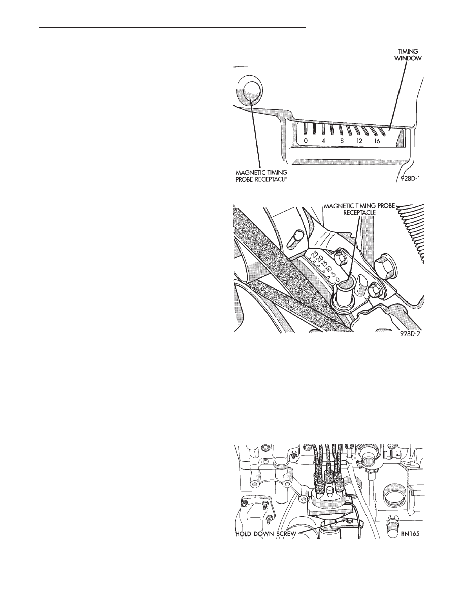
(2) If using a magnetic timing light, insert the

pickup probe into the open receptacle next to the
timing scale window. If a magnetic timing unit is not
available, use a conventional timing light connected to
the number one cylinder spark plug cable.

Do not puncture cables, boots or nipples with

test probes. Always use proper adapters. Punc-
turing the spark plug cables with a probe will
damage the cables. The probe can separate the
conductor and cause high resistance. In addition
breaking the rubber insulation may permit sec-
ondary current to arc to ground.

(3) Turn selector switch to the appropriate cylinder

position.

(4) Start engine and run until operating tempera-

ture is obtained.

(5) With the engine at normal operating tempera-

ture, connect the DRB II to the diagnostic connector.
Access the State Display screen. Refer to the appropri-
ate Powertrain Diagnostics Procedures Manual. If not
using the DRB II tester, disconnect the coolant
temperature sensor electrical connector. 
The
electric radiator fan will operate and the Check Engine
light will turn on after disconnecting the coolant sensor
or starting the DRB II procedure.

(6) Aim Timing Light at timing scale (Fig. 10 or Fig.

11) or read magnetic timing unit. If flash occurs when
timing mark is before specified degree mark, timing is
advanced. To adjust, turn distributor housing in direc-
tion of rotor rotation.

If flash occurs when timing mark is after specified

degree mark, timing is retarded. To adjust, turn dis-

tributor housing against direction of rotor rotation.
Refer to Vehicle Emission Control Information label for
correct timing specification. If timing is within

6 2° of

value specified on the label, proceed to step (8). If
outside specified tolerance, proceed to next step.

(7) Loosen distributor hold-down arm screw enough

to rotate the distributor housing (Fig. 12 or Fig. 13).
Turn distributor housing to adjust timing. Tighten the
hold-down arm screw and recheck timing.

Fig. 10 Timing Scale—2.5L Engine

Fig. 11 Timing Scale—3.0L Engine

Fig. 12 Distributor Holddown—2.5L Engine

.

IGNITION SYSTEMS

8D - 17

(8) Turn the engine off. Remove timing light or

magnetic timing unit and tachometer. If the coolant
temperature sensor was disconnected, connect the sen-
sor and erase fault codes using the Erase Fault
Code Mode on the DRBII. 
Refer to Group 14 General
Diagnosis, On Board Diagnostics.

DISTRIBUTOR—2.5L ENGINE

REMOVAL

(1) Disconnect distributor pick-up connector from

wiring harness connector (Fig. 14).

(2) Remove splash shield retaining screws (Fig. 15).
(3) Remove splash shield (Fig. 15).
(4) Loosen distributor cap retaining screws (Fig. 16).
(5) Lift cap off of distributor (Fig. 17).

(6) Rotate engine crankshaft until the distributor

rotor is pointing toward the cylinder block. Use this as
reference when reinstalling distributor.

(7) Remove distributor hold-down screw (Fig. 12).
(8) Carefully lift the distributor from the engine.

INSTALLATION

(1) Position distributor in engine. Make certain that

the O-ring is properly seated on distributor. If O-ring is
cracked or nicked, replace it with new one.

(2) Carefully engage distributor drive with auxiliary

shaft drive. When distributor is installed properly,
rotor will be pointing toward cylinder block. If engine
has been cranked while distributor is removed, it
will be necessary to establish proper relation-
ship between the distributor shaft and Number 1
piston position as follows:

Fig. 13 Distributor Holddown—3.0L Engine

Fig. 14 Distributor Pickup Connector—2.5L Engine

Fig. 15 Splash Shield—2.5L Engine

Fig. 16 Distributor Cap Retaining Screws—2.5L En-

gine

8D - 18

IGNITION SYSTEMS

.

(a) Rotate the crankshaft until number one piston

is at top of compression stroke. Pointer on clutch
housing should be in line with the O (TDC) mark on
flywheel.

(b) Rotate rotor to a position just ahead of the

number one distributor cap terminal.

(c) Lower the distributor into the opening, engag-

ing distributor drive with drive on auxiliary shaft.
With distributor fully seated on engine, rotor should
be under the cap number 1 tower.
(3) Install the distributor cap. Ensure all high ten-

sion wires snap firmly in the cap towers.

(4) Install hold-down arm screw and finger tighten.
(5) Install splash shield.
(6) Connect distributor pick-up connector lead wire

at wiring harness connector.

(7) Set ignition timing to specification. Refer to Ig-

nition Timing.

DISTRIBUTOR PICK-UP—2.5L ENGINE

REMOVAL

(1) Remove splash shield and cap. Refer to Distribu-

tor Removal.

(2) Remove rotor from shaft (Fig. 18).
(3) Remove Hall effect pick-up assembly (Fig.

19).

INSTALLATION

(1) Place pick-up assembly into distributor housing

(Fig. 19).

The distributor pick-up wires may be damaged

if not properly reinstalled.

(2) Install rotor (Fig. 18).

(3) Install cap and splash shield. Refer to Distribu-

tor Installation.

DISTRIBUTOR SERVICE—3.0L ENGINE

REMOVAL

(1) Disconnect distributor connector from wiring

harness connector (Fig. 20).

(2) Loosen distributor cap retaining screws.
(3) Lift cap of off distributor (Fig. 21).

Fig. 17 Distributor Cap—2.5L Engine

Fig. 18 Ignition Rotor—2.5L Engine

Fig. 19 Hall Effect Pickup Assembly—2.5L Engine

.

IGNITION SYSTEMS

8D - 19

(4) Rotate engine crankshaft until the distributor

rotor points the intake manifold plenum. Scribe a mark
on the plenum in line with the rotor. The scribe line
indicates where to position the rotor when reinstalling
the distributor.

(5) Remove distributor hold down nut (Fig. 22).
(6) Carefully lift the distributor from the engine.

INSTALLATION

(1) Position distributor in engine. Make certain that

the O-ring is properly seated on distributor. If O-ring is
cracked or nicked replace with new one.

(2) Carefully engage distributor drive with gear on

camshaft. When the distributor is installed properly,
the rotor will be in line with previously scribe line on
air intake plenum. If engine was cranked while
distributor was removed, it will be necessary to
establish proper relationship between the dis-
tributor shaft and Number 1 piston position as
follows:

(a) Rotate the crankshaft until number one piston

is at top of compression stroke.

(b) Rotate rotor to number one rotor terminal (Fig.

23).

(c) Lower the distributor into the opening, engag-

ing distributor drive with drive on camshaft. With
distributor fully seated on engine, rotor should be
under the number 1 terminal (Fig. 23).

(3) Install the distributor cap (Fig. 21). Ensure sure

all high tension wires are firmly in the cap towers.

(4) Install hold-down nut and finger tighten (Fig.

22).

(5) Connect distributor electrical connector to wiring

harness connector (Fig. 20).

(6) Set ignition timing to specification. Refer to Ig-

nition Timing in this section.

DISASSEMBLY

(1) Remove distributor cap mounting screws (Fig.

21).

Fig. 20 Distributor Electrical Connector—3.0L En-

gine

Fig. 21 Distributor Cap—3.0L Engine

Fig. 22 Distributor Hold-Down—3.0L Engine

Fig. 23 3.0L Engine Distributor Cap Terminal

Routing—View from Top of Cap

8D - 20

IGNITION SYSTEMS

.


Content   ..  200  201  202  203   ..