Chrysler Town & Country/Voyager, Dodge Caravan, Plymouth Voyager. Manual - part 195


  Index      Chrysler     Chrysler Town & Country/Voyager, Dodge Caravan, Plymouth Voyager - service repair manual 1992 year


Search            


Content   ..  193  194  195  196   ..


Chrysler Town & Country/Voyager, Dodge Caravan, Plymouth Voyager. Manual - part 195


BOSCH STARTER GEAR AND CLUTCH RE-
PLACEMENT

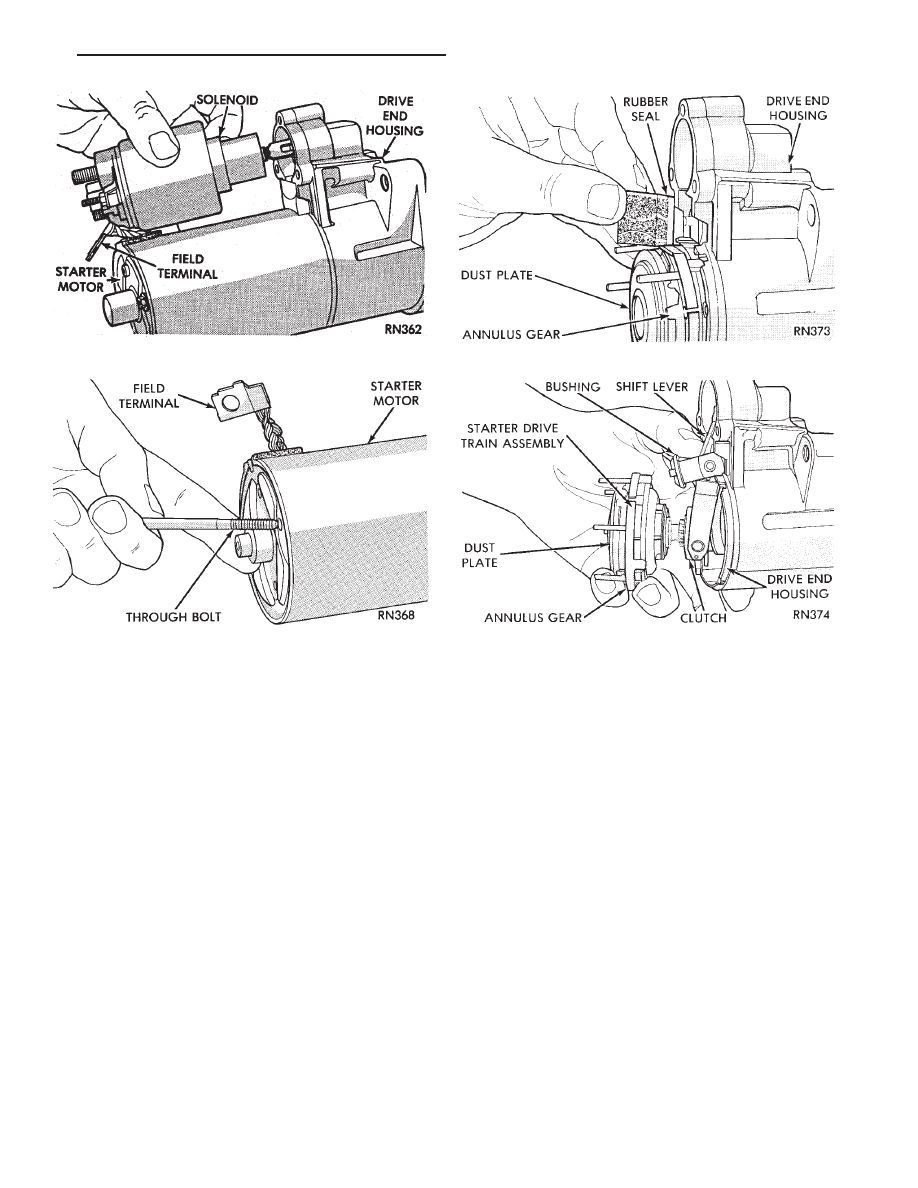
(1) Remove solenoid assembly (Fig. 18).
(2) Remove the two through-bolts securing the

starter drive end housing to the motor housing (Fig. 19)
and separate housings.

(3) Remove rubber seal (Fig. 20).
(4) Pull the gear and clutch assembly from the drive

end housing (Fig. 21).

(5) For installation, reverse above procedures.

NEUTRAL STARTING AND BACK-UP SWITCH

For electrical diagnostics, when checking the starter

circuits, refer to the STARTER RELAY TESTS chart in
Group 8A, Battery/Starting/Charging Systems Diag-
nostics.

For removal and installation of neutral switch, refer

to Neutral Switch Replacement in Group 21, Tran-
saxle.

Fig. 18 Solenoid

Fig. 19 Through-Bolt

Fig. 20 Rubber Seal

Fig. 21 Starter Drive Gear Train

.

BATTERY/STARTER/ALTERNATOR SERVICE

8B - 7

ALTERNATOR SERVICE PROCEDURES

INDEX

page

page

Alternator Replacement—2.5L Engine . . . . . . . . . . . 8
Alternator Replacement—3.0L Engine . . . . . . . . . . . 9

Alternator Replacement—3.3L Engine

. . . . . . . . . . 10

General Information

. . . . . . . . . . . . . . . . . . . . . . . . 8

GENERAL INFORMATION

This section will cover alternator replacement only.

Information covering alternator on-vehicle testing and
diagnosis

can

be

found

in

Group

8A,

Battery/Starting/Charging Systems Diagnostics. To
identify the alternator, refer to the Alternator Specifi-
cation chart at the rear of this section.

These alternators are not intended to be disas-

sembled for service. It must be replaced as an
assembly.

ALTERNATOR REPLACEMENT—2.5L ENGINE

Removal and repositioning of A/C Compressor with-

out disconnecting refrigerant lines is necessary on
some models to gain access to alternator.

(1) Disconnect battery negative cable (Fig. 1).

(2) If Equipped With air conditioning:

(a) Remove the A/C drive belt. Refer to Group 7,

Cooling System.

(b) Remove the four bolts retaining the A/C com-

pressor to the mounting bracket (Fig. 2).

(c) Do not disconnecting the A/C refrigerant lines,

position the A/C compressor to allow alternator re-
moval.

WARNING: THE A/C REFRIGERANT SYSTEM IS UN-
DER PRESSURE EVEN WHEN THE ENGINE IS OFF.
REFER TO THE SAFETY PRECAUTIONS AND WARN-
INGS SECTION IN HEATING AND A/C, GROUP 24,
BEFORE PERFORMING ANY SERVICE OPERATION.

(3) Remove the alternator drive belt. Refer to Group

7, Cooling System.

(4) Remove the two alternator mounting bolts (Fig.

3) and position the alternator to gain access to all the
wire connectors. If equipped with a :
• BOSCH ALTERNATOR. Remove B+ terminal nut,
field terminal nuts, and ground harness hold down
nuts (Fig. 4). Remove wire connector assembly.
• NIPPONDENSO ALTERNATOR. Remove nuts from
field

terminals,

ground

terminal,

wire

harness

Fig. 3 Remove or Install Mounting Bolts

Fig. 1 Remove Battery Negative (-) Cable

Fig. 2 A/C Compressor Removal and

Installation—2.5 L Engine

8B - 8

BATTERY/STARTER/ALTERNATOR SERVICE

.

and B+ terminal (Fig. 5). B+ terminal nut must be
removed last to prevent damage to terminal insulator.

(5) Remove the alternator from the vehicle.
(6) For

installation,

reverse

above

procedures.

Torque all fasteners. Refer to the TORQUE SPECIFI-
CATIONS chart at the rear of this group.

ALTERNATOR REPLACEMENT—3.0L ENGINE

(1) Disconnect battery negative cable (Fig. 1).
(2) Remove alternator drive belt. Refer to Group 7,

Cooling System.

(3) Remove the alternator mounting bolts and sepa-

rate the alternator from the mounting bracket (Fig. 6).

(4) Remove the B+ terminal nut, field terminal nuts,

and ground/wire harness hold-down nuts. Remove wire
connectors.

(5) Remove the alternator from the vehicle.
(6) For

installation,

reverse

above

procedures.

Torque all fasteners. Refer to the Torque Specifications
chart at the back of this group.

Fig. 4 Remove or Install Wire Connector

Assembly—Bosch Alternator

Fig. 5 Remove or Install Wire Connector

Assembly—Nippondenso Alternator

Fig. 6 Remove or Install Alternator Mounting

Bolts—3.0L Engine

Fig. 7 Support Bracket for Alternator Tensioner

Power Steering Bracket

.

BATTERY/STARTER/ALTERNATOR SERVICE

8B - 9

ALTERNATOR REPLACEMENT—3.3L ENGINE

(1) Disconnect battery NEGATIVE cable (Fig. 1).
(2) Remove alternator drive belt. Refer to Group 7,

Cooling System.

(3) Loosen, but do not remove the nut on the support

bracket at exhaust manifold (Fig. 7).

(4) Remove the alternator tensioner power steering

bracket bolt.

(5) Remove the tensioner stud nut and the tensioner

(Fig. 8).

(6) Remove the alternator mounting bolts.
(7) Remove and position the power steering reser-

voir from the alternator mounting bracket. Do not
remove the hoses from the reservoir.

(8) Remove the three alternator support bracket

bolts (Fig. 7).

(9) Remove intake plenum-to-alternator mounting

bracket bolt.

(10) Remove alternator support bracket (Fig. 8).
(11) Position alternator and remove alternator wir-

ing.

(12) Remove alternator.
(13) For installation, reverse above procedures.

Torque all fasteners. Refer to the Torque Specifications
chart at the back of this group.

SPECIFICATIONS

Fig. 8 Alternator/Support Bracket—3.3L Engine

STARTER/BATTERY

8B - 10

BATTERY/STARTER/ALTERNATOR SERVICE

.


Content   ..  193  194  195  196   ..