Chrysler Town & Country/Voyager, Dodge Caravan, Plymouth Voyager. Manual - part 191


  Index      Chrysler     Chrysler Town & Country/Voyager, Dodge Caravan, Plymouth Voyager - service repair manual 1992 year


Search            


Content   ..  189  190  191  192   ..


Chrysler Town & Country/Voyager, Dodge Caravan, Plymouth Voyager. Manual - part 191


• BOSCH STARTERS: Replace the solenoid

• NIPPONDENSO STARTERS: Replace the starter
assembly

ALTERNATOR TEST PROCEDURES ON VEHICLE

INDEX

page

page

Current Output Test

. . . . . . . . . . . . . . . . . . . . . . 17

Output Wire Resistance Test

. . . . . . . . . . . . . . . . 15

OUTPUT WIRE RESISTANCE TEST

The alternator output wire resistance test shows the

amount of voltage drop across the alternator output
wire between the alternator B+ terminal and the
positive battery post.

PREPARATION

Before starting test, make sure the vehicle has a fully

charged battery. Tests and procedures to check for a
fully charged battery are shown in the Battery section
of this Group.

(1) Turn the ignition switch OFF.
(2) Disconnect battery negative cable.

(3) Disconnect the alternator B+ output wire from

the alternator output battery terminal (Fig. 1).

(4) Connect a 0-150 ampere scale (DC) ammeter in

series between B+ terminal and output wire (Fig. 1 and
2). Connect positive lead to B+ terminal, and negative
lead to output wire.

(5) Using 0-18 volt scale voltmeter, connect the posi-

tive lead to the disconnected (B+) output wire. Connect
the negative lead to positive battery cable at positive
post.

(6) Remove fresh air hose between Engine Control-

ler and air cleaner if necessary.

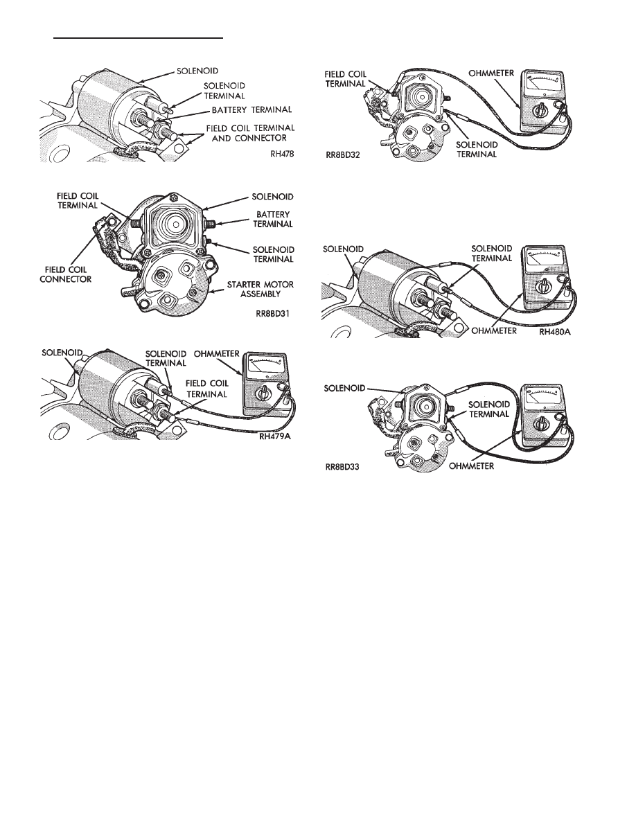
Fig. 15 Field Coil Wire Terminal—Bosch

Fig. 16 Field Coil Wire Terminal—Nippondenso

Fig. 17 Continuity Test Between Solenoid Terminal

and Field Coil Terminal—Bosch

Fig. 18 Continuity Test Between Solenoid Terminal

and Field Coil Terminal—Nippondenso

Fig. 19 Continuity Test Between Solenoid Terminal

and Solenoid Case —Bosch

Fig. 20 Continuity Test Between Solenoid Terminal

and Solenoid Case —Nippondenso

.

BATTERY/STARTING/CHARGING SYSTEMS DIAGNOSTICS

8A - 15

(7) Connect jumper wire between a good ground, and

K20 circuit terminal at the back of the alternator.

CAUTION: Do not connect the A142 circuit terminal
(Fig. 1) to ground the Fusible link will burn.

(8) Connect an engine tachometer and connect bat-

tery negative cable.

(9) Connect a volt/amp tester equipped with a vari-

able carbon pile rheostat between battery terminals
(Fig. 3).

Caution: Be sure the carbon pile is in OFF position
before connecting leads.

TEST

(1) Start engine. Immediately after starting, reduce

engine speed to idle.

Fig. 2 Alternator Output Wire Resistance Test

Fig. 3 Volt/Amp Tester Connections

Fig. 1 Alternator Wiring Connections

8A - 16

BATTERY/STARTING/CHARGING SYSTEMS DIAGNOSTICS

.

(2) Adjust engine speed and carbon pile to maintain

20 amperes flowing in the circuit. Observe voltmeter
reading. Voltmeter reading should not exceed 0.5 volts.

RESULTS

If a higher voltage drop is shown, inspect, clean and

tighten all connections between alternator B+ terminal
and battery positive post. A voltage drop test may be
performed at each connection to locate a connection
with excessive resistance. If resistance tests are satis-
factory, reduce engine speed, turn off carbon pile, and
turn off ignition switch.

(1) Disconnect battery negative cable.
(2) Remove test ammeter, voltmeter, carbon pile,

and tachometer.

(3) Remove jumper wire.
(4) Connect output wire to B+ terminal.
(5) Connect battery negative cable.
(6) Connect fresh air hose between Engine Control-

ler and air cleaner if removed.

CURRENT OUTPUT TEST

The current output test determines whether or not

the alternator is capable of delivering its rated current
output. For alternator identification and output am-
perage specifications, refer to Alternator Specifica-
tions.

For alternator maximum voltage at individual tem-

peratures, refer to Alternator Output Voltage Specifi-
cations.

PREPARATION

Before starting any tests, make sure the vehicle has

a fully charged battery. Tests and procedures to check
for a fully charged battery are shown in Battery
section.

(1) Disconnect battery negative cable.
(2) Disconnect output wire at the B+ terminal (Figs.

1 and 4).

(3) Connect a 0-150 ampere scale (DC) ammeter in

series between the B+ terminal and output wire. Con-
nect Positive lead to B+ terminal and negative lead to
output wire.

(4) Using 0-18 voltmeter, connect the positive lead to

B+ terminal (Figs. 2 and 4). Connect negative lead to a
good ground.

(5) Connect an engine tachometer and connect bat-

tery negative cable.

(6) Connect a volt/amp tester equipped with a vari-

able carbon pile rheostat between battery terminals
(Fig. 5). Be sure carbon pile is in OFF position before
connecting leads.

(8) Remove fresh air hose between Engine Control-

ler and air cleaner if necessary.

Fig. 4 Alternator Current Output Test

.

BATTERY/STARTING/CHARGING SYSTEMS DIAGNOSTICS

8A - 17

(9) Full field the alternator. Connect a jumper wire

between a good ground and to the K20 circuit terminal
at the back of the alternator (Figs. 1 and 4).

CAUTION: Do not connect the A142 circuit terminal
(Fig. 1) to ground the Fusible link will burn.

TEST

(1) Start the engine. Immediately after starting,

reduce engine speed to idle.

(2) Adjust the carbon pile and engine speed in steps

until an engine speed of 1250 rpm, and a voltmeter
reading of 15 volts is obtained.

CAUTION: Do not allow the battery voltage to exceed
16 volts.

(3) The alternator amperage must meet the output

requirements for the particular alternator being
tested. Refer to Alternator Specifications for alternator
identification and amperage outputs.

RESULTS

(1) If amperage reading is less than specified, and

alternator output wire resistance is not excessive
(found from the previous tests), alternator should be
replaced. Refer to Alternator replacement in Group 8B,
Battery/Starter/Alternator Service. These alternators
are not intended to be disassembled for service. It must
be replaced as an assembly.

(2) After current output test is completed, reduce

engine speed, turn off carbon pile, and turn off ignition
switch.

(3) Disconnect battery negative cable.
(4) Remove test ammeter, voltmeter, tachometer and

carbon pile.

(5) Remove jumper wire between K20 circuit termi-

nal and ground.

(6) Connect output wire to B+ terminal.
(7) Connect negative battery cable.
(8) Connect fresh air hose between Engine Control-

ler and air cleaner if removed.

FAULT CODES—ON BOARD DIAGNOSTICS

INDEX

page

page

Diagnostic Testing Using Fault Codes

. . . . . . . . . . 19

Drb II Diagnostic Tester

. . . . . . . . . . . . . . . . . . . . 22

General Description/Information

. . . . . . . . . . . . . . 18

GENERAL DESCRIPTION/INFORMATION

Another way of diagnosing charging system prob-

lems can be accomplished using the On-Board Diag-
nostic System Fault Codes.

A Fault Code shows a potential problem in a moni-

tored circuit,

or a condition caused by a faulty component. A Fault

Code can be retrieved by turning the ignition switch
ON-OFF-ON-OFF-ON without starting the engine,
and counting the possible number of flashes of the
CHECK ENGINE LAMP in the instrument cluster.

EXAMPLES:

• If the Check Engine Lamp flashes four times,
pauses, and flashes one more time, a Code 41 is shown.
The first set of four flashes indicates the number four.
The second set of one flash indicates one.
• If the Check Engine Lamp flashes four times,
pauses, and flashes six more times, a Code 46 is shown.
The first set of four flashes indicates the number four.
The second set of six flashes indicates six.
• If the Check Engine Lamp flashes four times,
pauses, and flashes seven more times, a Code 47 is

Fig. 5 Volt/Amp Tester Connections

8A - 18

BATTERY/STARTING/CHARGING SYSTEMS DIAGNOSTICS

.


Content   ..  189  190  191  192   ..