Chrysler Town & Country/Voyager, Dodge Caravan, Plymouth Voyager. Manual - part 189
WARNING: NEVER EXCEED 20 AMPS WHEN CHARG-
ING A COLD -1°C (30°F) BATTERY. PERSONAL IN-
JURY MAY RESULT.
CHARGING COMPLETELY DISCHARGED BAT-
TERY
The following procedure should be used to recharge a
completely discharged battery. Unless procedure is
properly followed, a good battery may be needlessly
replaced (Fig. 16).
(1) Measure the voltage at battery posts with a
voltmeter accurate to 1/10 volt (Fig. 17). If below 10
volts, charge current will be low, and it could take some
time before it accepts a current in excess of a few
milliamperes. Such low current may not be detectable
on amp meters built into many chargers.
(2) Connect charger leads. Some chargers feature
polarity protection circuitry that prevents operation
unless charger is connected to battery posts correctly. A
completely discharged battery may not have enough
voltage to activate this circuitry. This may happen
though the leads are connected properly.
(3) Battery chargers vary in the amount of voltage
and current they provide. For the time required for the
battery to accept measurable charger current at vari-
ous voltages, refer to Fig. 16. If charge current is still
not measurable after charging times, the battery
should be replaced. If charge current is measurable
during charging time, the battery may be good, and
charging should be completed in the normal manner.
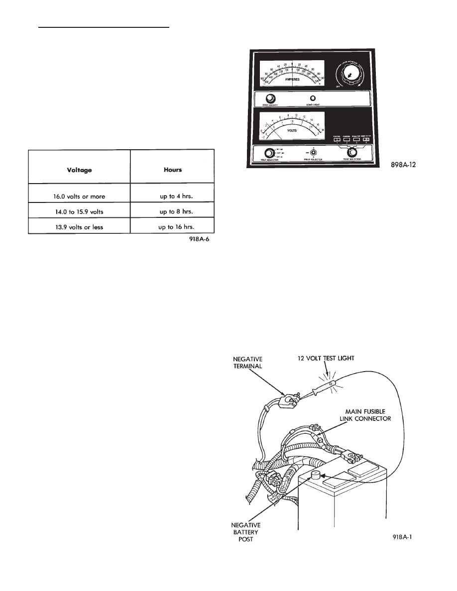
IGNITION OFF DRAW (IOD)
GENERAL INFORMATION
A normal electrical system will draw from 5 to 30
milliamperes from the battery. This is with the ignition
in the OFF position, and all non-ignition controlled
circuits in proper working order. The amount of IOD
will depend on body model and electrical components. A
vehicle that has not been operated for an extended
period approximately 20 days may discharge the bat-
tery to an inadequate level. In this case, the MAIN
Fusible Link Connector should be disconnected. The
Main Fusible Link connector is located rearward of the
battery on the engine wiring harness (Fig. 18).
If the IOD is over 30 milliamperes, the defect must be
found and corrected before replacing the battery. Usu-
ally, the battery can be charged and returned to service
(Fig. 15).
Fig. 16 CHARGE RATE
Fig. 17 Voltmeter Accurate to 1/10 Volt (Connected)
Fig. 18 IOD Test
.
BATTERY/STARTING/CHARGING SYSTEMS DIAGNOSTICS
8A - 7