Chrysler Town & Country/Voyager, Dodge Caravan, Plymouth Voyager. Manual - part 182


  Index      Chrysler     Chrysler Town & Country/Voyager, Dodge Caravan, Plymouth Voyager - service repair manual 1992 year


Search            


Content   ..  180  181  182  183   ..


Chrysler Town & Country/Voyager, Dodge Caravan, Plymouth Voyager. Manual - part 182


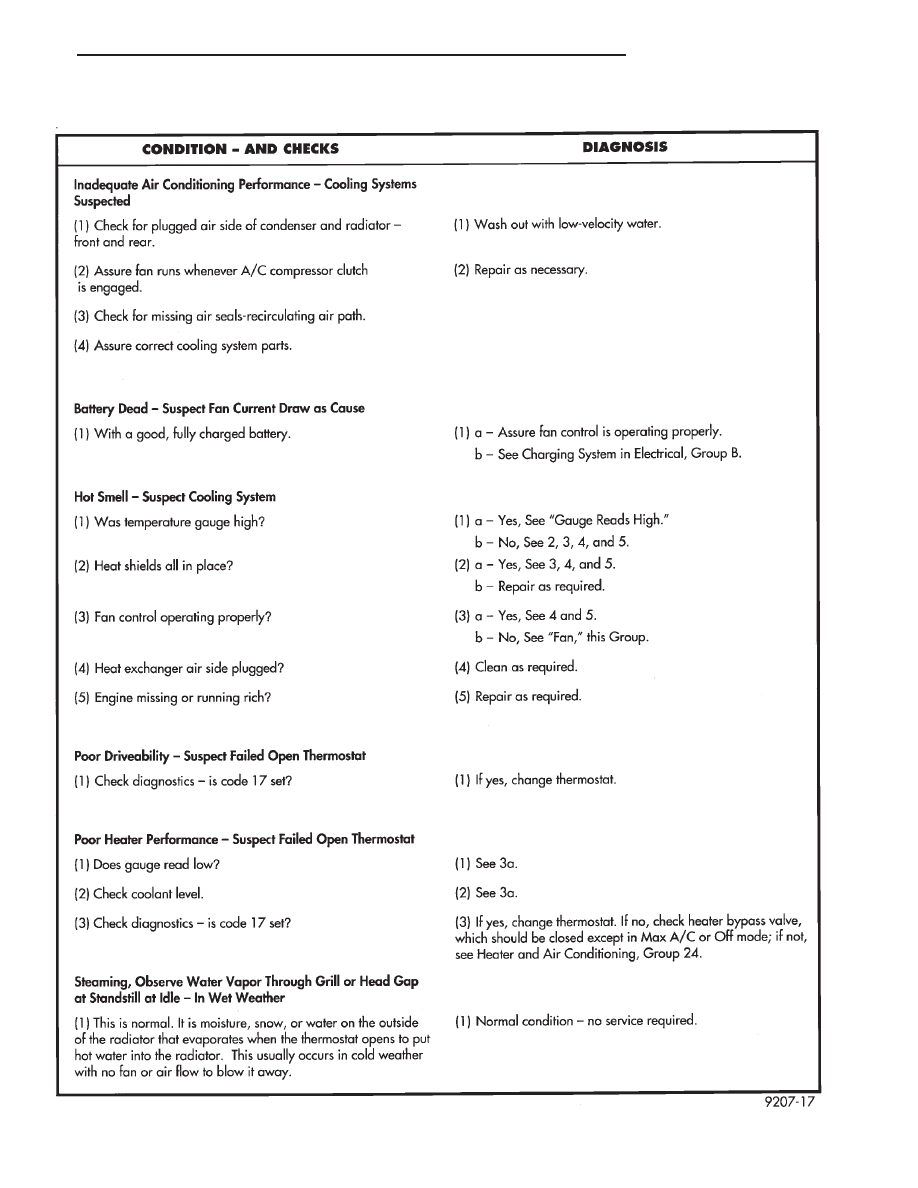
COOLING SYSTEM DIAGNOSIS

.

COOLING SYSTEM

7 - 9

SERVICE PROCEDURES

WATER PUMPS

A quick test to tell whether the pump is working is to

see if the heater warms properly. A defective pump can
not circulate heated coolant through the long heater
hose.

The water pump on all models can be replaced

without discharging the air conditioning system.

WATER PUMP 2.5L ENGINE

The 2.5L engine water pump has a diecast aluminum

body and housing with a stamped steel impeller. The
2.5L pump uses an O-ring gasket between body and
housing. The assembly bolts directly to the block.
Cylinder block to water pump sealing uses a rubber
O-ring.

REMOVAL

(1) Drain cooling system. Refer to Draining Cooling

System in this group.

(2) If equipped with air conditioning, see Solid

Mount Accessory Bracket in (Standard Service Proce-
dures) Group 9, Engine:

(a) Remove air conditioning compressor and alter-

nator from solid mount bracket and set aside. It is
not necessary to discharge the a/c system.

(b) Remove solid mount bracket.

(3) If the vehicle is not equipped with air condition-

ing, remove alternator and mounting bracket.

(4) Disconnect lower radiator and heater hoses from

pump.

(5) Remove water pump attaching screws to engine

(Fig. 1).

DISASSEMBLY

(1) Remove three screws holding pulley to water

pump.

(2) Remove nine screws holding water pump body to

housing. Remove the pump body from housing. (Fig. 2)

(3) Clean gasket surfaces on water pump housing

and engine block.

(4) Remove and discard O-ring gaskets and clean

O-ring grooves.

INSPECTION

Replace water pump body assembly if it has any of

these defects:

(1) Cracks or damage on the body.
(2) Water leaks from the shaft seal, evident by

coolant traces below the vent hole.

(3) Loose or rough turning bearing.
(4) Impeller rubs either the pump body or the hous-

ing.

ASSEMBLY

Body assembly and housing are serviced as separate

components.

(1) Install new O-ring gasket in body O-ring groove.
(2) Assemble pump body to housing and tighten nine

screws to 12 N

Im (105 in. lbs.) (Fig. 2).

(3) Rotate pump by hand to check for freedom of

movement.

(4) Position water pump pulley to water pump. In-

stall three screws and tighten to 30 N

Im (250 in. lbs.).

(5) Position new O-ring in housing to block O-ring

groove.

Fig. 1 Water Pump 2.5L Engines

Fig. 2 2.5L Water Pump Components

7 - 10

COOLING SYSTEM

.

INSTALLATION

(1) Install water pump on engine. Tighten top three

screws (Fig. 1) to 30 N

Im (250 in. lbs.). Install lower

screw and tighten to 68 N

Im (50 ft. lbs.).

(2) Reinstall bypass/heater hose and lower radiator

hose.

(3) Reinstall alternator and air conditioning com-

pressor bracket(s). For solid mount bracket see stan-
dard service procedures in Group 9 Engine.

(4) Reinstall alternator and air conditioning com-

pressor.

(5) Refill cooling system. See Refilling Cooling

System.

(6) Install drive belt, See Accessory Drive Belts, this

Group.

WATER PUMP 3.0L ENGINE

The 3.0L pump bolts directly to the engine block,

using a gasket for pump to block sealing (Fig. 3). The
pump is serviced as a unit.

The water pump is driven by the timing belt. See

Timing System in Group 9, Engine for component
removal providing access to water pump.

REMOVAL

(1) Drain cooling system. Refer to Draining Cooling

System in this group.

(2) Remove mounting bolts.
(3) Separate pump from water inlet pipe (Figs. 3 and

4) and remove.

INSPECTION

Replace the water pump if it has any of the following

defects.

(1) Damage or cracks on the pump body.
(2) Coolant leaks, if the shaft seal is leaking, evident

by traces of coolant leaks from vent hole A in (Fig. 4).

(3) Impeller rubs the inside of pump.
(4) Loose or rough turning bearing.

INSTALLATION

(1) Clean all gasket and O-ring surfaces on pump

and water pipe inlet tube.

(2) Install new O-ring on water inlet pipe (Fig. 5).

Wet the O-ring (with water) to ease assembly.

CAUTION: Keep the O-ring free of oil or grease.

(3) Install new gasket on water pump and install

pump inlet opening over water pipe, press assembly to
cause water pipe insertion into pump housing.

(4) Install pump to block mounting bolts and tighten

to 27 N

Im (20 ft. lbs.).

(5) See Timing System in Engine, Group 9 and

install timing belt. Reassemble engine.

(6) Fill cooling system. See Refilling Cooling System.

WATER PUMP 3.3L ENGINE

The 3.3L pump has a die cast aluminum body and a

stamped steel impeller. It bolts directly to the chain
case cover, using an O-ring for sealing. It is driven by
the back surface of the Poly-V Drive Belt.

Fig. 3 Water Pump 3.0L Engine

Fig. 4 Water Pump Inspection

Fig. 5 Water Pipe O-Ring

.

COOLING SYSTEM

7 - 11

REMOVAL

(1) Drain Cooling System. Refer to Draining Cooling

System in this group.

(2) Remove Poly V Drive Belt.
(3) Remove right front lower fender shield.
(4) Remove pump pulley bolts and remove pulley.
(5) Remove pump mounting screws (Fig. 6). Remove

pump.

(6) Remove and discard O-ring seal.
(7) Clean O-ring groove and O-ring surfaces on

pump and chain case cover. Take care not to scratch or
gouge sealing surface.

INSPECTION

Replace the water pump if it has any of the following

defects.

(1) Damage or cracks on the pump body.
(2) Coolant leaks; if the seal is leaking, evident by

traces of coolant leaks from vent hole.

(3) Loose or rough turning bearing.
(4) Impeller rubs either the pump body or chain case

cover.

INSTALLATION

(1) Install new O-ring in O-ring groove (Fig. 7).
(2) Install pump to chain case cover. Torque screws

to 12 N

Im (105 in. lbs.)

(3) Rotate pump by hand to check for freedom of

movement.

(4) Position pulley on pump. Install screws and

torque to 30 N

Im (250 in. lbs.).

(5) Install drive belt. See Accessory Drive Belts this

group.

(6) Install right front lower fender shield.
(7) Refill Cooling System. See Refilling Cooling Sys-

tem.

ENGINE THERMOSTAT

The 2.5L engine thermostat is located on the front of

the engine (radiator side) in the waterbox that is part
of the cylinder head construction (Fig. 8).

These thermostats do not have an air bleed notch.
The 3.0L engine thermostat is in a water box, formed

in the timing belt end of the intake manifold. This
thermostat has an air bleed valve, located in the
thermostat flange (Fig. 9).

The 3.3L engine thermostat is in a water box, formed

in the drive belt side of the intake manifold (Fig. 11).

DESCRIPTION AND OPERATION

The engine cooling thermostats are wax pellet

driven, reverse poppet choke type. They are designed
to provide the fastest warm up possible by preventing
leakage through them and to guarantee a minimum
engine operating temperature of 88 to 93°C (192 to
199°F). They also automatically reach wide open so
they do not restrict flow to the radiator as temperature
of the coolant rises in hot weather to around 104°C
(220°F). Above this temperature the coolant tempera-
ture is controlled by the radiator, fan, and ambient
temperature, not the thermostat.

OPERATION AND TESTING

The thermostat operateds by a wax filled container

(pellet) that is sealed so that when heated to a prede-
termined temperature. The wax expands enough to
overcome the closing spring and water pump pressure,
which forces the valve to open. Coolant leakage into the
pellet will cause a thermostat to fail open. Do not
attempt to free up a thermostat with a screwdriver.

The open too soon type failure mode is included in

the on-board diagnosis. The check engine light will not
be lit by an open too soon condition. Only if the
thermostat has failed open, a code 17 will be set. Do not
change a thermostat for lack of heat by gauge or heater
performance, unless code 17 is present, see diagnosis
for other probable causes. Failing shut is the normal
long term mode of failure, and normally, only

Fig. 6 Water Pump 3.3L Engine

Fig. 7 Water Pump Body

7 - 12

COOLING SYSTEM

.


Content   ..  180  181  182  183   ..