Chrysler Town & Country/Voyager, Dodge Caravan, Plymouth Voyager. Manual - part 134


  Index      Chrysler     Chrysler Town & Country/Voyager, Dodge Caravan, Plymouth Voyager - service repair manual 1992 year


Search            


Content   ..  132  133  134  135   ..


Chrysler Town & Country/Voyager, Dodge Caravan, Plymouth Voyager. Manual - part 134


To install, reverse the preceding operation using a

new O-ring seal. Evacuate and charge the refrigerant
system.

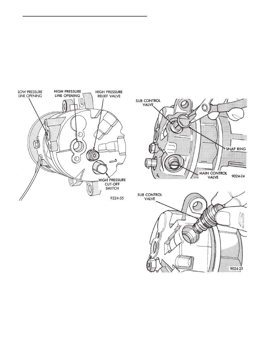
COMPRESSOR HIGH PRESSURE RELIEF VALVE

REMOVAL AND INSTALLATION

(1) Discharge the refrigerant system.
(2) Rotate the high pressure relief valve counter-

clockwise and separate relief valve from the vehicle
(Fig. 19).

To install, reverse the preceding operation using a

new O-ring seal. Evacuate and charge the refrigerant
system.

COMPRESSOR MAIN OR SUB CONTROL VALVES

If the main or sub control valve is leaking refrigerant

to the atmosphere, replace the main or sub control
valve. If a functional problem is suspected with the
main or sub control valve, the compressor should be
replaced.

REMOVAL AND INSTALLATION

(1) Discharge the refrigerant system.
(2) Remove the compressor assembly. Position it to

gain access to the control valves. It is not necessary to
disconnect the suction or discharge lines from the
compressor.

(3) Remove the snap ring retaining either the main

or sub control valve to the compressor (Fig. 20).

(4) Pull the main or sub control valve from the

compressor end cover (Fig. 21).

To install, reverse the preceding operation using new

O-ring seals. Evacuate and charge the refrigerant
system.

Fig. 19 High Pressure Relief Valve Removal

Fig. 20 Main or Sub Control Valve Snap Ring

Fig. 21 Remove or Install Main or Sub Control Valve

.

HEATING AND AIR CONDITIONING

24 - 31

FIXED DISPLACEMENT COMPRESSOR SERVICE PROCEDURES

INDEX

page

page

Compressor Clutch/Coil Assembly—

Model 10PA17

. . . . . . . . . . . . . . . . . . . . . . . . . 32

Compressor Front Shaft Seal—Model 10PA17

. . . 34

Compressor High-Pressure Relief Valve

. . . . . . . . 36

Compressor Removal and Installation

. . . . . . . . . . 32

COMPRESSOR REMOVAL AND INSTALLATION

The A/C compressor may be removed and positioned

without discharging the refrigerant system. Discharg-
ing is not necessary if removing the A/C compressor
clutch/coil assembly, engine, cylinder head or alterna-
tor.

WARNING: Refrigerant pressures remain high even
though the engine may be turned off. Before remov-
ing a fully charged compressor, review the Safety
Precautions and Warnings section in this Group. Do
not twist or kink the refrigerant lines when removing
a fully charged compressor. Safety glasses must be
worn.

If the A/C compressor refrigerant lines will be re-

moved for compressor removal. Refer to Discharging
Refrigerant System in the Refrigerant Service Proce-
dures section before proceeding with the following
steps.

(1) Disconnect negative battery cable.
(2) Loosen and remove drive belts (refer to Group 7,

Cooling System) and disconnect compressor clutch
wire lead.

(3) Remove refrigerant lines from compressor (if

necessary).

(4) Remove compressor attaching nuts and bolts

(Fig. 1).

(5) Remove compressor. If refrigerant lines were not

removed, lift compressor/clutch assembly and tie it to a
suitable component.

To install, reverse the preceding operation.

COMPRESSOR CLUTCH/COIL—MODEL 10PA17

REMOVAL

Compressor assembly must be removed from mount-

ing. Although, refrigerant discharge is not necessary.

(1) Remove the compressor shaft bolt (Fig. 2). A band

type oil filter removal tool can be placed around the
clutch plate to aid in bolt removal.

(2) Tap the clutch plate with a plastic hammer and

remove clutch plate and shim (Fig. 3).

CAUTION: Do not use screwdrivers between the
clutch plate assembly and pulley to remove front
plate as this may damage the front plate assembly.

(3) Remove pulley retaining snap ring with snap

ring pliers (C-4574), and slide pulley assembly off of
compressor (Fig. 4).

Fig. 1 A/C Compressor Removal and

Installation—2.5 L Engines

Fig. 2 Compressor Shaft Bolt and Clutch Plate

24 - 32

HEATING AND AIR CONDITIONING

.

(4) Remove coil wire clip screw and wire harness.
(5) Remove snap ring retaining field coil onto com-

pressor housing (Fig. 5). Slide field coil off of compres-
sor housing.

(6) Examine frictional faces of the clutch pulley and

front plate for wear. The pulley and front plate should
be replaced if there is excessive wear or scoring. If the
friction surfaces are oily, inspect the shaft nose area of
the compressor for oil and remove the felt from the
front cover. If the compressor felt is saturated with oil,
the shaft seal is leaking and will have to be replaced.

(7) Check bearing for roughness, excessive leakage

or grease. If grease from bearing has contaminated the
faces of the pulley or front plate, or if the bearing is
rough, the clutch pulley and front plate should be
replaced.

CAUTION: The clutch pulley and the front plate were
mated at the factory by a burnishing operation. No
attempt should be made to separately replace either
part. This will result in clutch slippage due to insuf-
ficient contact area.

INSTALLATION

(1) Align pin in back of field coil with hole in com-

pressor end housing, and position field coil into place.
Make sure that lead wires are properly routed, and
fasten with the wire clip retaining screw.

(2) Install field coil retaining snap ring (bevel side

outward and both eyelets to the right or left of the pin
on the compressor) with SNAP RING PLIERS. Press
snap ring to make sure it is properly seated in the
groove.

CAUTION: If snap ring is not fully seated it will vibrate
out, resulting in a clutch failure and severe damage to
the front face of the compressor.

(3) Install pulley assembly to compressor. If neces-

sary, tap gently with a block of wood on the friction
surface (Fig. 6).

CAUTION: Do not mar the pulley frictional surface.

(4) Install pulley assembly retaining snap ring

(bevel side outward) with snap ring pliers. Press the
snap ring to make sure it is properly seated in the
groove.

Fig. 3 Clutch Plate and Shim(s)

Fig. 4 Removing Pulley Snap Ring

Fig. 5 Clutch Coil Snap Ring

.

HEATING AND AIR CONDITIONING

24 - 33

(5) If the original front plate assembly and pulley

assembly are to be reused, the old shim(s) can be used.
If not, place a trial stack of shims, 2.54 mm (0.10 in.)
thick, on the shaft against the shoulder.

(6) Install front plate assembly onto shaft.
(7) With the front plate assembly tight against the

shim(s), measure the air gap between front plate and
pulley face with feeler gauges. The air gap should be
between 0.5 and 0.9 mm (.020 and .035 inch) If proper
air gap is not obtained, add or subtract shims until
desired air gap is obtained.

(8) Install compressor shaft bolt. Tighten to 17.5

62

N

Im (155620 in. lbs.).

Shims may compress after tightening shaft nut.

Check air gap in four or more places to verify if
air gap is still correct. Spin pulley for final check.

CLUTCH BREAK-IN

After a new clutch has been installed, check the

voltage and amperage to the clutch (determine it to be
satisfactory). Then cycle the A/C clutch approximately
20 times (5 sec. on and 5 sec. off). For this procedure,
set the system to the A/C mode, using high blower, and
engine rpm at 1500-2000. This procedure (burnishing)
will seat the opposing friction surfaces and provide a
higher clutch torque capability.

COMPRESSOR FRONT SHAFT SEAL—MODEL
10PA17

REMOVAL

(1) Discharge the refrigerant system.
(2) Remove A/C compressor.
(3) Remove compressor clutch/coil assembly.
(4) Remove compressor through-bolts (Fig. 7).

(5) Remove front cover by tapping on the outside

diameter of the cover with a plastic hammer (Fig. 8).

(6) Remove and discard steel valve plate gasket and

O-ring seal (Fig. 9 and 10).

Never reuse cover O-rings or the steel valve

plate gaskets.

(7) Pry out the felt retainer and remove felt from

front cover (Fig. 11).

(8) Remove seal snap ring (Fig. 12).

Fig. 6 Installing Pulley Assembly

Fig. 7 Compressor Through-Bolts

Fig. 8 Removing Front Cover

24 - 34

HEATING AND AIR CONDITIONING

.


Content   ..  132  133  134  135   ..