Chrysler Town & Country/Voyager, Dodge Caravan, Plymouth Voyager. Manual - part 132


  Index      Chrysler     Chrysler Town & Country/Voyager, Dodge Caravan, Plymouth Voyager - service repair manual 1992 year


Search            


Content   ..  130  131  132  133   ..


Chrysler Town & Country/Voyager, Dodge Caravan, Plymouth Voyager. Manual - part 132


REFRIGERANT RECYCLING

(R-12) refrigerant is a chlorofluorocarbon (CFC) that

can contribute to the depletion of the ozone layer in the
upper atmosphere. Ozone filters out harmful radiation
from sunlight. To assist in protecting the ozone layer,
an (R-12) refrigerant recycling device that meets SAE
standard J1991 should be used. Contact an automotive
service equipment supplier for refrigerant recycling

equipment. Refer to the operating instructions pro-
vided with the recycling equipment for proper opera-
tion.

MANIFOLD GAUGE SET CONNECTIONS

GENERAL INFORMATION

The high pressure (discharge) (RED) hose should be

attached to the 1/4 in. discharge service port. This port
will be located on the discharge line between the air
conditioning compressor and the condenser, or on the
high pressure (liquid) line.

The low pressure (suction) (BLUE) hose should be

attached to the 3/8 in. suction service port. This port is
located on either the air conditioning compressor, or
the suction line between the expansion valve and the
compressor.

SUCTION (LOW PRESSURE) GAUGE CONNECTION

(1) Remove the service port cap from 3/8 in. suction

service port.

(2) Check all valves on the equipment being used to

verify they are closed.

(3) Inspect the hose gasket in the service port con-

nector at the end of the (BLUE) hose. If the gasket is
flawed, replace it.

(4) Thread the hose connector onto the service port

until the valve core depressor in the hose end makes
contact with the valve core in the service port. Quickly
secure hose connector to the service port to avoid
loosing refrigerant.

To disconnect suction gauge (BLUE) hose:

(a) Wrap the end of hose with a shop towel.
(b) Loosen the hose connector.

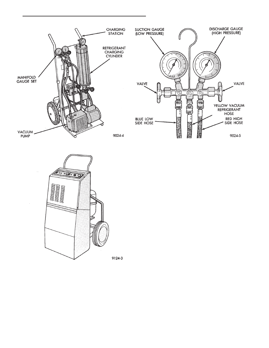
Fig. 2 Refrigerant Charging Station—Typical

Fig. 3 Refrigerant Recovery/Recycling

Station—Typical

Fig. 4 Manifold Gauge Set—Typical

.

HEATING AND AIR CONDITIONING

24 - 23

(c) Push and hold the end of hose toward the

service port to keep the gasket in contact with service
port.

(d) Quickly rotate the connector counterclockwise.

When the hose connector is completely backed off,
immediately point the end of hose toward floor, as
possibly trapped refrigerant in the hose will be
released.

(e) Install service port cap.

DISCHARGE (HIGH PRESSURE) GAUGE CONNECTION

(1) Remove the service port cap from the 1/4 in.

service port.

(2) Check all valves on the equipment being used to

verify they are closed.

(3) Inspect the hose gasket in the service port con-

nector at the end of the (RED) hose. If the gasket is
flawed, replace it.

(4) Use a suitable (3/8 in. male to 1/4 in. female)

adapter (Fig. 5), threaded securely into the end of the
(RED) hose connector.

(5) Start threading the 1/4 in. hose adapter connec-

tor onto the service port. Thread until the valve core
depressor in the adapter makes contact with the valve
core in the service port. Quickly secure adapter connec-
tor to service port to avoid loosing refrigerant.

To disconnect the discharge gauge (RED) hose:

(a) Wrap the end of hose with a shop towel.
(b) Loosen the hose connector.
(c) Push and hold the end of hose toward the

service port to keep the gasket in contact with service
port.

(d) Quickly rotate the connector counterclockwise.

When the hose connector is completely backed off,
immediately point the end of hose toward floor, as
possibly trapped refrigerant in the hose will be
released.

(e) Install service port cap.

EVACUATION/RECOVERY/RECYCLING/CHARGING LINE CON-
NECTION

The center manifold (YELLOW) or (WHITE) hose is

used to discharge, recycle, recover, evacuate, and
charge the refrigerant system. When the discharge or

suction valves on the manifold gauge set are opened,
the refrigerant in the system will escape through this
hose.

It is recommended that this hose be attached to

a refrigerant (R-12) Recovery/Recycling device.
Refer to the operators manual for procedures.

For disconnection of this hose, refer to Disconnecting

the Discharge Gauge (RED) hose in the preceding
paragraphs.

TESTING FOR REFRIGERANT LEAKS

If the A/C system is not cooling the passenger com-

partment, determine if the refrigerant system is fully
charged. If the refrigerant system is empty or low in
refrigerant charge, a leak at any line fitting or compo-
nent seal is likely. To detect a leak in the refrigerant
system, perform one of the following procedures as
indicated by the symptoms.

EMPTY REFRIGERANT SYSTEM LEAK TEST

CAUTION: Review Safety Precautions and Warnings
in General Information section of this Group.

(1) Evacuate the refrigerant system to the lowest

degree of vacuum possible.

(2) Prepare a 10 oz. refrigerant (R-12) charge to be

injected into the system.

(3) Connect and dispense 10 ozs. of refrigerant into

the evacuated refrigerant system.

(4) Proceed to step two of Low Refrigerant Level

Leak Test.

LOW REFRIGERANT LEVEL LEAK TEST

Caution: Review Safety Precautions and Warnings in
the General Information section of this group.

(1) Using the refrigerant level sight glass, determine

if there is any (R-12) refrigerant in the system.

(2) Position the vehicle in a wind free work area.

This will aid in detecting small leaks.

(3) Bring the refrigerant system up to operating

temperature and pressure by allowing the engine to
run for approximately five minutes.

(4) With the engine not running, use an Electronic

Leak Detector (or equivalent) and search for leaks.
Fittings, lines, or components that appear to be oily
usually will indicate a refrigerant leak. To inspect the
evaporator core for leaks, it is possible to insert the
leak detector probe into the recirculating air door
opening (Fig. 6).

ADDING PARTIAL REFRIGERANT CHARGE

If it was not necessary to completely discharge the

refrigerant system, a partial refrigerant charge can be
added to the system.

Fig. 5 Discharge Hose Adapter

24 - 24

HEATING AND AIR CONDITIONING

.

CAUTION: Review all Safety Precautions and Warn-
ings in the General Information Section before adding
refrigerant to the system. Do not add refrigerant to a
system that is known to have a leak.

(1) Attach manifold gauge set.
(2) Open the windows of the passenger compartment

and set the air-conditioning controls to A/C, RECIRC,
and Low blower speed.

(3) Start the engine and allow it to warm up to

normal running temperature.

(4) If the air-conditioning compressor does not en-

gage, disconnect the low pressure cut-off switch. Place
a jumper wire across the terminals in the connector
boot. If the compressor still does not engage, a problem
exists in the compressor clutch feed circuit.

(5) Hold the engine speed at 1400 rpm.
(6) While following the instructions provided with

the charging equipment being used, charge through
the suction side of the system. Add enough refrigerant
to clear the sight glass in the filter drier.

(7) At the point when the sight glass clears, note the

weight of the refrigerant supply drum or the level in
the charging cylinder. Add an additional 340 g (12 oz) of
refrigerant to the system. Remove the jumper wire
from the low pressure cut-off switch connector and
connect the cut-off switch.

(8) Test the over all performance of the air-

conditioner. Close all valves on the charging equipment
and disconnect the hoses from the service ports. Install
the service port caps.

DISCHARGING REFRIGERANT SYSTEM

(R-12) refrigerant is a chlorofluorocarbon (CFC) that

can contribute to the depletion of the ozone layer in the
upper atmosphere. Ozone filters out harmful radiation
from sunlight. To assist in protecting the ozone layer,
Chrysler Corporation recommends that an (R-12) re-
frigerant recycling device that meets SAE standard
J1991 be used. Use this device when it is necessary to
discharge the refrigerant system. Contact an automo-
tive service equipment supplier for refrigerant recy-
cling equipment. Refer to the operating instructions
provided with the recycling equipment for proper op-
eration.

EVACUATING REFRIGERANT SYSTEM

If the air-conditioning refrigerant system has been

open to the atmosphere, it must be evacuated before
the system can be charged with refrigerant. Moisture
and air mixed with the refrigerant will raise the
compressor head pressure above acceptable operating
levels. This will reduce the performance of the air-
conditioner and damage the compressor. Moisture will
boil at near room temperature when exposed to
vacuum. To evacuate the refrigerant system:

(1) Connect a suitable charging station, refrigerant

recovery machine, and a manifold gauge set with
vacuum pump.

(2) Open the suction and discharge valves and start

the vacuum pump. When the suction gauge reads -88
kPa (-26 in. Hg) vacuum or greater, close all valves and
turn off vacuum pump. If the system fails to reach
specified vacuum, the refrigerant system likely has a
leak that must be corrected. If the refrigerant system
maintains specified vacuum for at least 30 minutes,
start the vacuum pump, open the suction and dis-
charge valves. Then allow the system to evacuate an
additional 10 minutes.

(3) Close all valves. Turn off and disconnect the

vacuum pump.

The refrigerant system is prepared to be charged

with refrigerant.

Fig. 6 Testing for A/C Leaks—Typical Front/Rear A/C

System

.

HEATING AND AIR CONDITIONING

24 - 25

CHARGING REFRIGERANT SYSTEM—EMPTY SYS-
TEM

CAUTION: Do not over charge refrigerant system, as
excessive compressor head pressure can cause
noise and system failure.

WARNING: REVIEW SAFETY PRECAUTIONS AND
WARNINGS IN GENERAL INFORMATION SECTION
OF THIS GROUP BEFORE CHARGING THE REFRIG-
ERANT SYSTEM.

After the refrigerant system has been tested for leaks

and evacuated, a refrigerant (R-12) charge can be
injected into the refrigerant system.

(1) Connect manifold gauge set.
(2) Measure refrigerant (refer to capacities) and

heat to 52°C (125°F) with the charging station. Refer to
the instructions provided with the equipment being
used.

REFRIGERANT CAPACITIES:

• Without Rear A/C = 964 g (34 oz.)

• With Rear A/C = 1276 g (45 oz.)

(3) Open the suction and discharge valves. Open the

charge valve to allow the heated refrigerant to flow into
the system. When the transfer of refrigerant has
stopped, close the suction and discharge valve.

(4) If all of the refrigerant charge did not transfer

from the dispensing device, start the engine and run
engine at a high idle (1400 rpm). Set the A/C control to
A/C, low blower speed, and open windows. If the A/C
compressor does not engage, test the compressor clutch
control circuit and correct any failure. Refer to Group
8W, Wiring Diagrams.

(5) Open the suction valve to allow the remaining

refrigerant to transfer to the system.

WARNING: TAKE CARE NOT TO OPEN THE DIS-
CHARGE (HIGH-PRESSURE) VALVE AT THIS TIME.

(6) Close all valves and test the A/C system perfor-

mance.

(7) Disconnect the charging station or manifold

gauge set. Install the service port caps.

OIL LEVEL

It is important to have the correct amount of oil in

the A/C system to ensure proper lubrication of the
compressor. Too little oil will result in damage to the
compressor. Too much oil will reduce the cooling capac-
ity of the system and consequently result in higher
discharge air temperatures.

The oil used in the compressor is a 500 SUS viscosity,

wax-free refrigerant oil. Only refrigerant oil of the
same type should be used to service the system. Do not
use any other oil. The oil container should be kept
tightly capped until it is ready for use, and then tightly

capped after use to prevent contamination from dirt
and moisture. Refrigerant oil will quickly absorb any
moisture it comes in contact with.

It will not be necessary to check oil level in the

compressor or to add oil unless there has been an oil
loss. This may be due to a ruptured line, shaft seal
leakage, leakage from the evaporator, condenser leak,
filter drier or loss of refrigerant due to a collision. Oil
loss at a the leak point will be evident by the presence
of a wet, shiny surface around the leak.

REFRIGERANT OIL LEVEL CHECK

When an air-conditioning system is first assembled

at the factory, all of the components (except the com-
pressor) are refrigerant oil free. After the system has
been charged with (R12) refrigerant and operated, the
oil in the compressor is dispersed through the lines and
components. The evaporator, condenser, and filter-
drier will retain a significant amount of oil. (Refer to
the Refrigerant Oil Capacities chart). When a compo-
nent is replaced, the specified amount of refrigerant oil
must be added. When the compressor is replaced, the
amount of oil that is retained in the rest of the system
must be drained from the replacement compressor.
When a refrigerant line or component has ruptured
and has released an unknown amount of oil, the
compressor should be removed and drained through
the suction port. The filter-drier must be replaced
along with the ruptured part. The oil capacity of the
system, minus the amount of oil still in the remaining
components, can be measured and poured into the
suction port of the compressor.

Example:The evaporator retains 60 ml (2 oz). The

condenser retains 30 ml (1 oz) of oil, and system
capacity may be 214 ml (7.25 oz) of oil.

214 ml minus 90 ml = 124 ml (4.25 oz).

VERIFY REFRIGERANT OIL LEVEL

(1) Slowly discharge refrigerant system.
(2) Remove refrigerant lines from A/C compressor.
(3) Remove compressor from vehicle.
(4) From suction port on top of compressor, drain

refrigerant oil from compressor.

REFRIGERANT OIL CAPACITIES

24 - 26

HEATING AND AIR CONDITIONING

.


Content   ..  130  131  132  133   ..