Content .. 2758 2759 2760 2761 ..
Chevrolet Silverado / GMC Sierra. Manual - part 2760
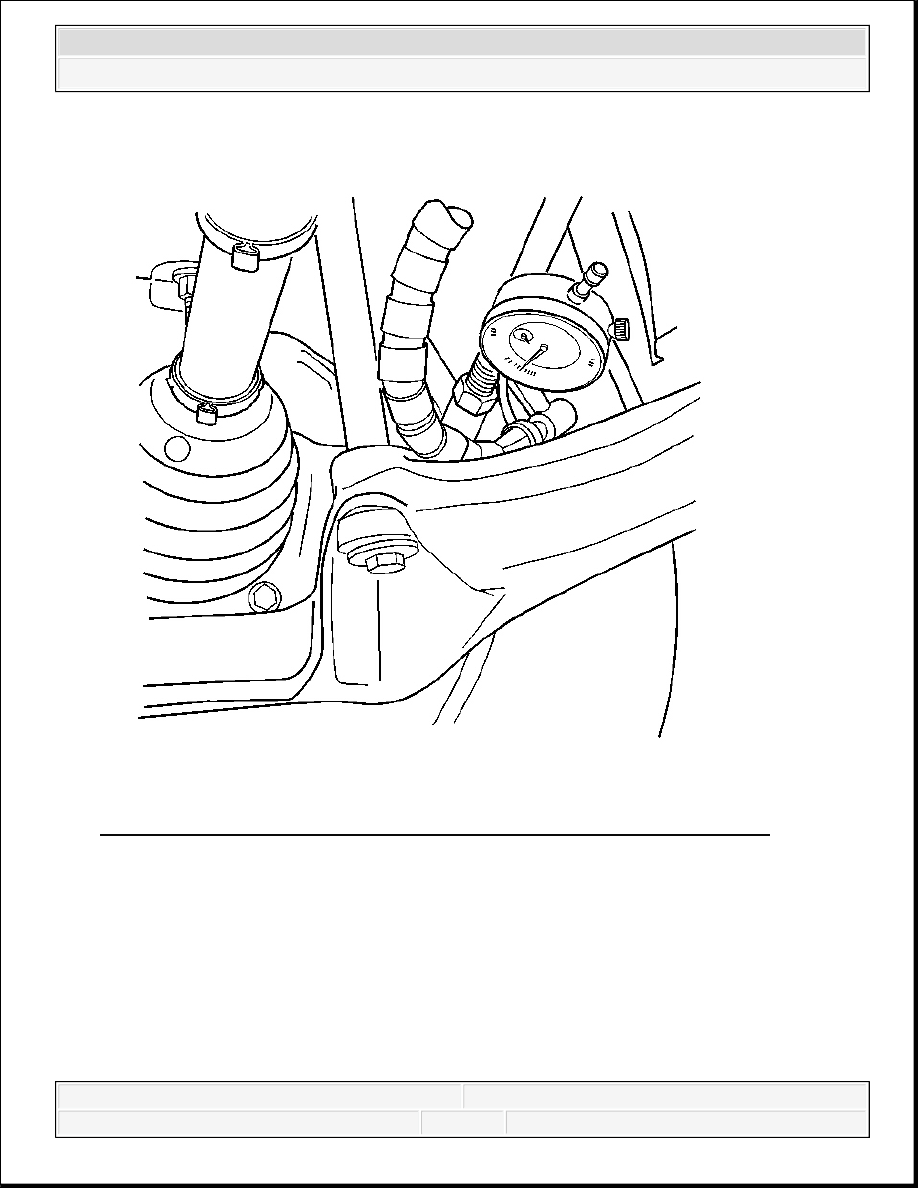
Fig. 3: Installing Dial Indicator Between Outer Tie Rod End And Jam Nut
Courtesy of GENERAL MOTORS CORP.
5. Install the dial indicator between the steering linkage outer tie rod and the steering linkage
inner tie rod nut and attach the other end to the relay rod as shown and push slowly inward
on the tire with one hand to remove the lash.
6. Place the dial indicator at zero, pull outward, and note the amount of movement in the joint.
The movement should not exceed 1.0 mm (0.039 in).
2008 Chevrolet Silverado 1500
2008 STEERING Steering Linkage - Cab & Chassis Sierra, Cab & Chassis Silverado, Sierra & Silverado

Fig. 4: Installing Dial Indicator Between Pitman Arm And Relay Rod
Courtesy of GENERAL MOTORS CORP.
7. Install the dial indicator between the pitman arm and the relay rod as shown and push
slowly inward on the tire with one hand to remove the lash.
2008 Chevrolet Silverado 1500
2008 STEERING Steering Linkage - Cab & Chassis Sierra, Cab & Chassis Silverado, Sierra & Silverado

Fig. 5: Measuring Amount Of Movement In Left Side Joint
Courtesy of GENERAL MOTORS CORP.
8. Place the dial indicator at zero, pull outward, and note the amount of movement in the joint.
The movement should not exceed 1.0 mm (0.039 in).
2008 Chevrolet Silverado 1500
2008 STEERING Steering Linkage - Cab & Chassis Sierra, Cab & Chassis Silverado, Sierra & Silverado

Fig. 6: Elevating Right Front Of Vehicle
Courtesy of GENERAL MOTORS CORP.
9. Elevate the right front of vehicle and install a suitable vehicle support maintaining contact
between the left front tire/wheel assembly and the shop floor.
2008 Chevrolet Silverado 1500
2008 STEERING Steering Linkage - Cab & Chassis Sierra, Cab & Chassis Silverado, Sierra & Silverado
Content .. 2758 2759 2760 2761 ..