Chevrolet Silverado / GMC Sierra. Manual - part 270

Fig. 123: View Of Cylinder Head Gasket Displacement Markings
Courtesy of GENERAL MOTORS CORP.
5. Inspect the displacement markings (2) on the gasket, for proper usage.
2008 Hummer H2
2008 ENGINE Engine Mechanical - 6.2L - H2

Fig. 124: View Of Right Cylinder Head Gasket And Alignment Pins
Courtesy of GENERAL MOTORS CORP.
6. Install the NEW right cylinder head gasket onto the locating pins.
IMPORTANT: When properly installed, the tab on the right cylinder head
gasket will be located right of center or closer to the front of
the engine.
2008 Hummer H2
2008 ENGINE Engine Mechanical - 6.2L - H2

Fig. 125: View Of Right Cylinder Head
Courtesy of GENERAL MOTORS CORP.
7. Install the cylinder head onto the locating pins and gasket.
8. Install the NEW cylinder head bolts.
2008 Hummer H2
2008 ENGINE Engine Mechanical - 6.2L - H2
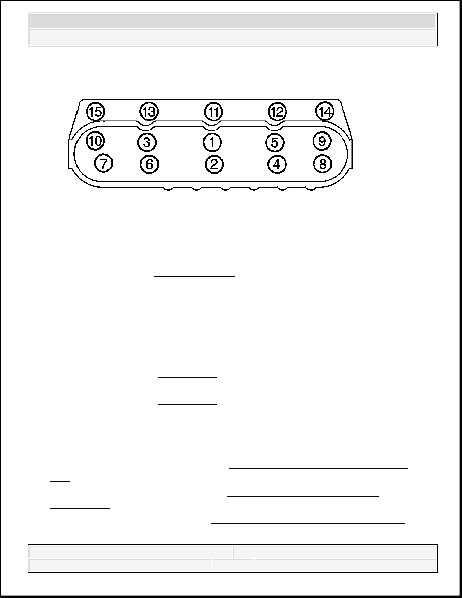
Fig. 126: Cylinder Head Bolt Tightening Sequence
Courtesy of GENERAL MOTORS CORP.
9. Tighten the cylinder head bolts.
Tighten:
1. Tighten the M11 cylinder head bolts (1-10) a first pass in sequence to 30 N.m (22 lb
ft).
2. Tighten the M11 cylinder head bolts (1-10) a second pass in sequence to 90 degrees
using J 45059 . See Special Tools.
3. Tighten the M11 cylinder head bolts (1-10 ) a final pass in sequence to 70 degrees
using J 45059 . See Special Tools.
4. Tighten the M8 cylinder head bolts (11-15) to 30 N.m (22 lb ft). Begin with the center
bolt (11) and alternating side-to-side, work outward tightening all of the bolts.
10. Install the pushrods. Refer to Valve Rocker Arm and Push Rod Replacement.
11. Install the right exhaust manifold. Refer to Exhaust Manifold Replacement - Right
Side .
12. Install the coolant air bleed pipe. Refer to Coolant Air Bleed Pipe Assembly
Replacement .
13. Install the oil level indicator. Refer to Oil Level Indicator and Tube Replacement.
VALVE LIFTER REPLACEMENT
NOTE:
Refer to Fastener Notice .
2008 Hummer H2
2008 ENGINE Engine Mechanical - 6.2L - H2