Content .. 2378 2379 2380 2381 ..
Chevrolet Silverado / GMC Sierra. Manual - part 2380

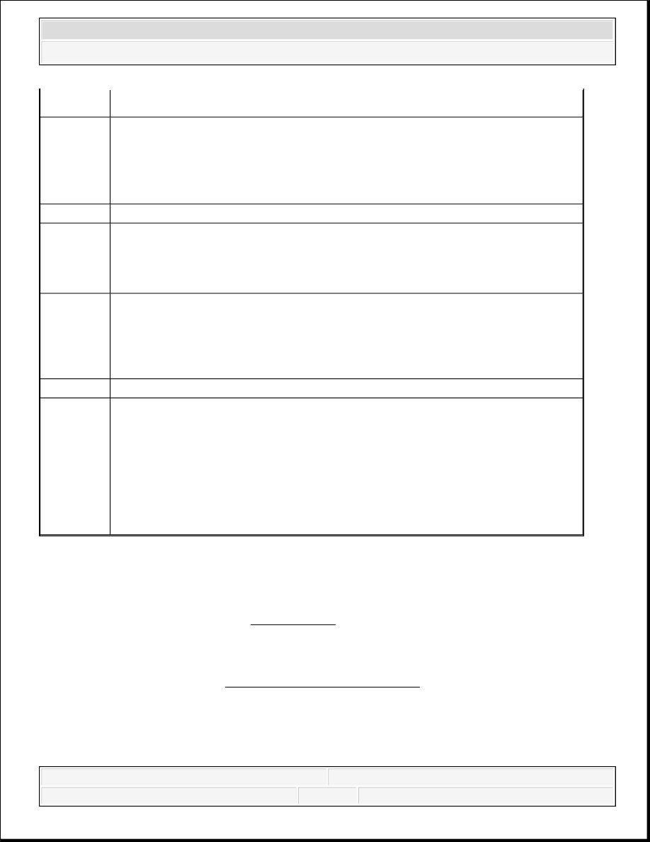
Fig. 14: Bleeding Master Cylinder
Courtesy of GENERAL MOTORS CORP.
1. Secure the mounting flange of the brake master cylinder in a bench vise so that the rear of
the primary piston is accessible.
2. Remove the master cylinder reservoir cap and diaphragm.
3. Install suitable fittings to the master cylinder ports that match the type of flare seat required
and also provide for hose attachment.
4. Install transparent hoses to the fittings installed to the master cylinder ports, then route the
hoses into the master cylinder reservoir.
5. Fill the master cylinder reservoir to at least the half-way point with Delco Supreme 11®,
GM P/N 12377967 (Canadian P/N 992667), or equivalent DOT-3 brake fluid from a clean,
sealed brake fluid container.
2008 Chevrolet Silverado 1500
2008 BRAKES Hydraulic Brakes - Cab & Chassis Sierra, Cab & Chassis Silverado, Sierra & Silverado

6. Ensure that the ends of the transparent hoses running into the master cylinder reservoir are
fully submerged in the brake fluid.
7. Using a smooth, round-ended tool, depress and release the primary piston as far as it will
travel, a depth of about 25 mm (1 in), several times. Observe the flow of fluid coming from
the ports.
As air is bled from the primary and secondary pistons, the effort required to depress the
primary piston will increase and the amount of travel will decrease.
8. Continue to depress and release the primary piston until fluid flows freely from the ports
with no evidence of air bubbles.
9. Remove the transparent hoses from the master cylinder reservoir.
10. Install the master cylinder reservoir cap and diaphragm.
11. Remove the fittings with the transparent hoses from the master cylinder ports. Wrap the
master cylinder with a clean shop cloth to prevent brake fluid spills.
12. Remove the master cylinder from the vise.
BRAKE FLUID LEVEL INDICATOR SWITCH REPLACEMENT (JD9, JF3, JF7)
Fig. 15: Brake Fluid Level Indicator Switch Replacement (JD9, JF3, JF7)
2008 Chevrolet Silverado 1500
2008 BRAKES Hydraulic Brakes - Cab & Chassis Sierra, Cab & Chassis Silverado, Sierra & Silverado

Courtesy of GENERAL MOTORS CORP.
BRAKE PEDAL ASSEMBLY REPLACEMENT
Fig. 16: Brake Pedal Assembly Replacement
Courtesy of GENERAL MOTORS CORP.
Callout
Component Name
Preliminary Procedure:
Disconnect the master cylinder fluid level sensor electrical connector.
1
Master Cylinder Fluid Level Sensor
Tip: Compress the locking tabs on the sensor to release the sensor from the
brake master cylinder reservoir.
Callout
Component Name
Preliminary Procedure:
Apply the park brake.
1
Brake Booster Pushrod Retainer Bolt
NOTE:
Refer to Fastener Notice .
2008 Chevrolet Silverado 1500
2008 BRAKES Hydraulic Brakes - Cab & Chassis Sierra, Cab & Chassis Silverado, Sierra & Silverado
BRAKE PIPE REPLACEMENT
Tools Required
J 45405 Pipe Flaring Tool Kit. See Special Tools.
Replacement
Tighten: 10 N.m (89 lb in)
2
Brake Booster Pushrod Retainer
Procedure:
After installing the retainer to the pushrod pin on the brake pedal, rotate the
retainer 360 degrees to ensure it is seated properly before tightening the retainer
bolt.
3
Stoplamp Switch
4
Brake Booster Pushrod
Procedure:
For reassembly, apply a thin coat of high temperature grease GM P/N
12345994 (Canadian P/N 10953501) to the pushrod pin on the brake pedal.
5
Brake Pedal Pivot Nut
Procedure:
Hold the brake pedal pivot bolt stationary and tighten the brake pedal pivot nut.
Tighten: 35 N.m (26 lb ft)
6
Brake Pedal Pivot Bolt
7
Brake Pedal
Procedure
1. If installing a new brake pedal pivot bushing, ensure the conical flange end
of the bushing is on the inboard side of the pedal.
2. For reassembly, apply high temperature grease GM P/N 12345994
(Canadian P/N 10953501) to the ID of the brake pedal pivot bushing.
CAUTION: Refer to Brake Fluid Irritant Caution .
CAUTION: Always use double walled steel brake pipe when replacing
brake pipes. The use of any other pipe is not recommended
2008 Chevrolet Silverado 1500
2008 BRAKES Hydraulic Brakes - Cab & Chassis Sierra, Cab & Chassis Silverado, Sierra & Silverado
Content .. 2378 2379 2380 2381 ..