Content .. 2275 2276 2277 2278 ..
Chevrolet Silverado / GMC Sierra. Manual - part 2277
Seal Replacement (2500) or Front Wheel Hub, Bearing, and Seal Replacement
(1500).
5. Install the wheel drive shaft, if equipped. Refer to Wheel Drive Shaft Replacement
(2500) or Wheel Drive Shaft Replacement (1500) .
6. Install the tire and wheel. Refer to Tire and Wheel Removal and Installation .
7. Remove the support and lower the vehicle.
8. Verify the wheel alignment. Refer to Wheel Alignment Specifications .
UPPER CONTROL ARM REPLACEMENT (1500)
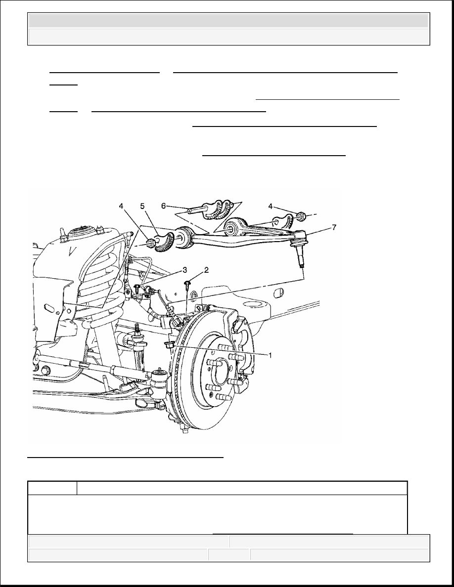
Fig. 12: View Of Upper Control Arm (1500)
Courtesy of GENERAL MOTORS CORP.
Callout
Component Name
Preliminary Procedures
1. Raise and support the vehicle. Refer to Lifting and Jacking the Vehicle .
2008 Chevrolet Silverado 1500
2008 SUSPENSION Front Suspension - Cab & Chassis Sierra, Cab & Chassis Silverado, Sierra & Silverado

UPPER CONTROL ARM REPLACEMENT (2500, 3500)
Tools Required
J-42188-B Ball Joint Separator. See Special Tools.
2. Remove the front tire and wheel assembly. Refer to Tire and Wheel Removal and
Installation .
1
Upper Ball Joint Nut
Procedure
1. Disconnect the electronic suspension control link connector.
2. Place a suitable support under the lower control arm and load the
suspension.
3. Use the J-42188-B to separate the ball joint from the steering knuckle.
See Special Tools.
Tighten: 50 N.m (37 lb ft)
Special Tool:
J-42188-B Ball Joint Separator. See Special Tools.
NOTE:
Refer to Fastener Notice .
2
Wheel Speed Sensor Wire Bolt
Tighten: 10 N.m (89 lb ft)
3
Brake Hose/Wheel Speed Sensor Harness Retainer Bolt
Tighten: 9 N.m (80 lb in)
4
Upper Control Arm Nut (Qty: 4)
Tighten: 190 N.m (140 lb ft)
5
Upper Control Arm Alignment Cam (Qty: 4)
6
Upper Control Arm Bolt (Qty: 2)
7
Upper Control Arm
Tip: Verify wheel alignment. Refer to Wheel Alignment Specifications
2008 Chevrolet Silverado 1500
2008 SUSPENSION Front Suspension - Cab & Chassis Sierra, Cab & Chassis Silverado, Sierra & Silverado

Removal Procedure
1. Remove the tire and wheel. Refer to Tire and Wheel Removal and Installation .
Fig. 13: Supporting Lower Control Arm
Courtesy of GENERAL MOTORS CORP.
2. Lower the vehicle and support the lower control arm.
3. Remove the retaining bolt for the brake hose and the wheel speed sensor brackets.
4. Remove the nut at the upper ball joint. Discard the nut.
2008 Chevrolet Silverado 1500
2008 SUSPENSION Front Suspension - Cab & Chassis Sierra, Cab & Chassis Silverado, Sierra & Silverado
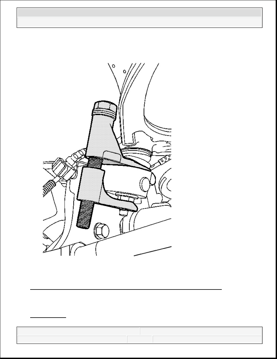
Fig. 14: View Of Special Tool At Upper Ball Joint & Steering Knuckle
Courtesy of GENERAL MOTORS CORP.
5. Disconnect the upper control arm from the steering knuckle using the J-42188-B . See
Special Tools.
2008 Chevrolet Silverado 1500
2008 SUSPENSION Front Suspension - Cab & Chassis Sierra, Cab & Chassis Silverado, Sierra & Silverado
Content .. 2275 2276 2277 2278 ..