Chevrolet Silverado / GMC Sierra. Manual - part 213

OIL LEVEL INDICATOR AND TUBE INSTALLATION
Fig. 716: Oil Level Indicator Tube Sealant
Courtesy of GENERAL MOTORS CORP.
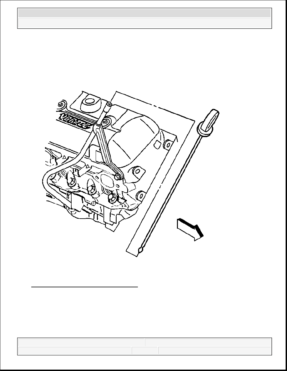
1. Apply sealant GM P/N 12346004 (Canadian P/N 10953480) or equivalent, around the oil
level indicator tube 13 mm (0.5 in) below the tube bead.
2. Install the oil level indicator tube into the engine block. Rotate the oil level indicator tube
into position.
NOTE:
Refer to Fastener Notice .
2008 Chevrolet Silverado 1500
2008 ENGINE Engine Mechanical - 4.3L - Sierra & Silverado
3. Install the oil level indicator tube bolt.
Tighten: Tighten the oil level indicator tube bolt to 12 N.m (106 lb in).
Fig. 717: Locating Oil Level Indicator
Courtesy of GENERAL MOTORS CORP.
4. Install the oil level indicator into the oil level indicator tube, if required.
WATER PUMP INSTALLATION
Tools Required
2008 Chevrolet Silverado 1500
2008 ENGINE Engine Mechanical - 4.3L - Sierra & Silverado

J 41240 Fan Clutch Remover and Installer. See Special Tools.
Installation
Fig. 718: View Of Water Pump & Bolts
Courtesy of GENERAL MOTORS CORP.
1. If reusing the fasteners, apply sealant GM P/N 12346004 (Canadian P/N 10953480) or
equivalent, to the threads of the water pump bolts.
2. Install the water pump and the NEW water pump gaskets.
3. Install the water pump bolts.
Tighten: Tighten the water pump bolts to 45 N.m (33 lb ft).
NOTE:
Refer to Fastener Notice
2008 Chevrolet Silverado 1500
2008 ENGINE Engine Mechanical - 4.3L - Sierra & Silverado

Fig. 719: View Of Water Pump Inlet Hose & Clamps
Courtesy of GENERAL MOTORS CORP.
4. Install the water pump inlet hose and the water pump inlet hose clamps.
IMPORTANT: After final assembly, the water pump inlet hose clamp tangs,
water pump end, must point forward and the upper tang
should be level with the outside diameter of the water pump
inlet hose.
2008 Chevrolet Silverado 1500
2008 ENGINE Engine Mechanical - 4.3L - Sierra & Silverado