Chevrolet Silverado / GMC Sierra. Manual - part 208

Fig. 698: Valve Rocker Arm Assemblies
Courtesy of GENERAL MOTORS CORP.
4. Install the valve rocker arm assemblies as follows:
1. Finger start the bolt at location (1)
2. Finger start the bolt at location (2)
3. Finger start the bolt at location (3)
4. Finger start the remaining valve rocker arm bolts
2008 Chevrolet Silverado 1500
2008 ENGINE Engine Mechanical - 4.3L - Sierra & Silverado

Fig. 699: View Of Crankshaft Balancer Alignment Mark & Engine Front Cover
Alignment Tab
Courtesy of GENERAL MOTORS CORP.
IMPORTANT: Rotate the number 1 cylinder to top dead center (TDC) of the
compression stroke. The engine front cover has 2 alignment
tabs and the crankshaft balancer has 2 alignment marks
which are spaced 90 degrees apart that are used for
positioning the number 1 piston at TDC.
2008 Chevrolet Silverado 1500
2008 ENGINE Engine Mechanical - 4.3L - Sierra & Silverado
5. Rotate the crankshaft balancer clockwise until the alignment marks on the crankshaft
balancer are aligned with the tabs on the engine front cover, 1 with 2 and 3 with 4. At that
point the number 1 piston should be at TDC of the compression stroke.
6. Tighten the valve rocker arm bolts.
Tighten: Tighten valve rocker arm bolts to 30 N.m (22 lb ft).
INTAKE MANIFOLD INSTALLATION
NOTE:
Refer to Fastener Notice .
IMPORTANT: Once the valve rocker arm assemblies are installed and
properly torqued, no additional valve lash adjustment is
required.
2008 Chevrolet Silverado 1500
2008 ENGINE Engine Mechanical - 4.3L - Sierra & Silverado
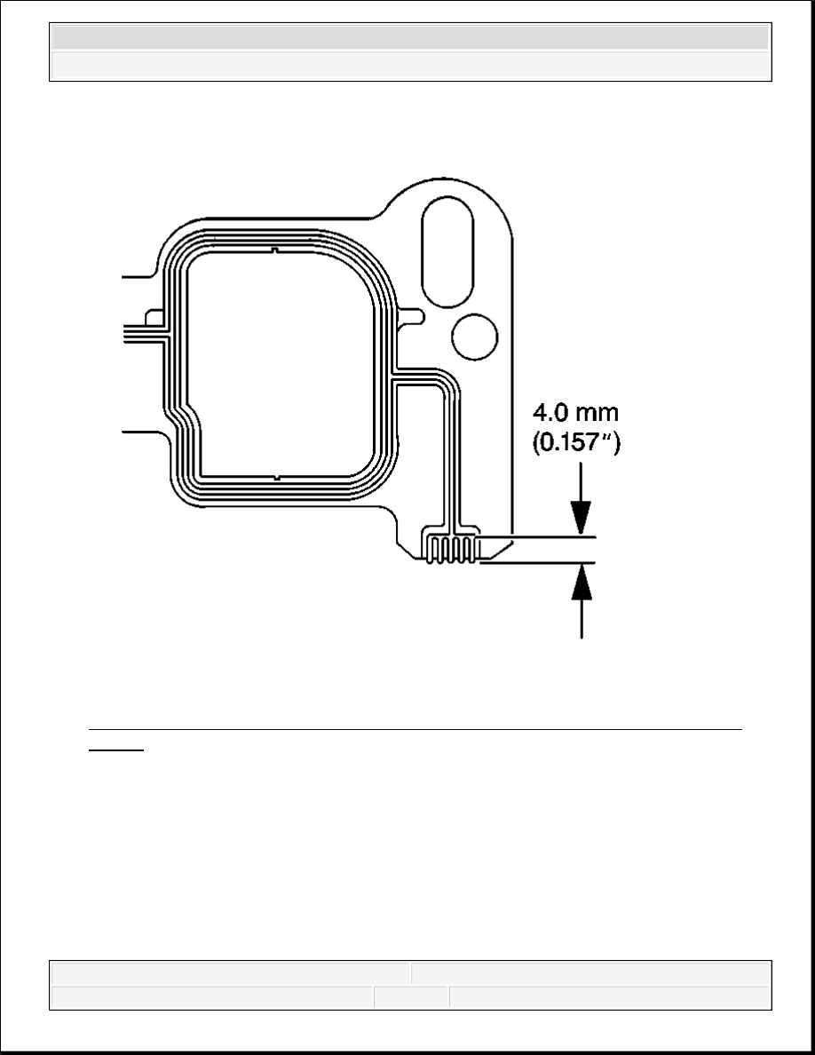
Fig. 700: Applying Patch Of Adhesive To Cylinder Head Side Of Intake Manifold
Gasket
Courtesy of GENERAL MOTORS CORP.
1. Apply a 4.0 mm (0.157 in) patch of adhesive GM P/N 12346141 (Canadian P/N 10953433)
or equivalent, to the cylinder head side of the lower intake manifold gasket at each end.
NOTE:
Apply the proper amount of the sealant when assembling this
component. Excessive use of the sealant can prohibit the
component from sealing properly. A component that is not
sealed properly can leak leading to extensive engine damage.
2008 Chevrolet Silverado 1500
2008 ENGINE Engine Mechanical - 4.3L - Sierra & Silverado