Content .. 1845 1846 1847 1848 ..
Chevrolet Silverado / GMC Sierra. Manual - part 1847
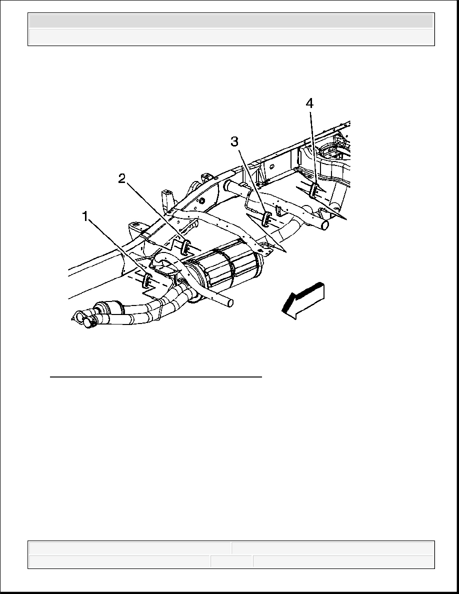
Fig. 209: View Of Muffler Assembly Insulators
Courtesy of GENERAL MOTORS CORP.
1. Lubricate the 4 insulators where the muffler assembly hangers are inserted in order to ease
installation.
2. With the aid of an assistant, position and install the muffler assembly.
3. Install the insulators (1-4) to the front, intermediate, and rear muffler assembly hangers.
2008 Chevrolet Silverado 1500
2008 ENGINE Engine Exhaust - Cab & Chassis Sierra, Cab & Chassis Silverado, Sierra & Silverado
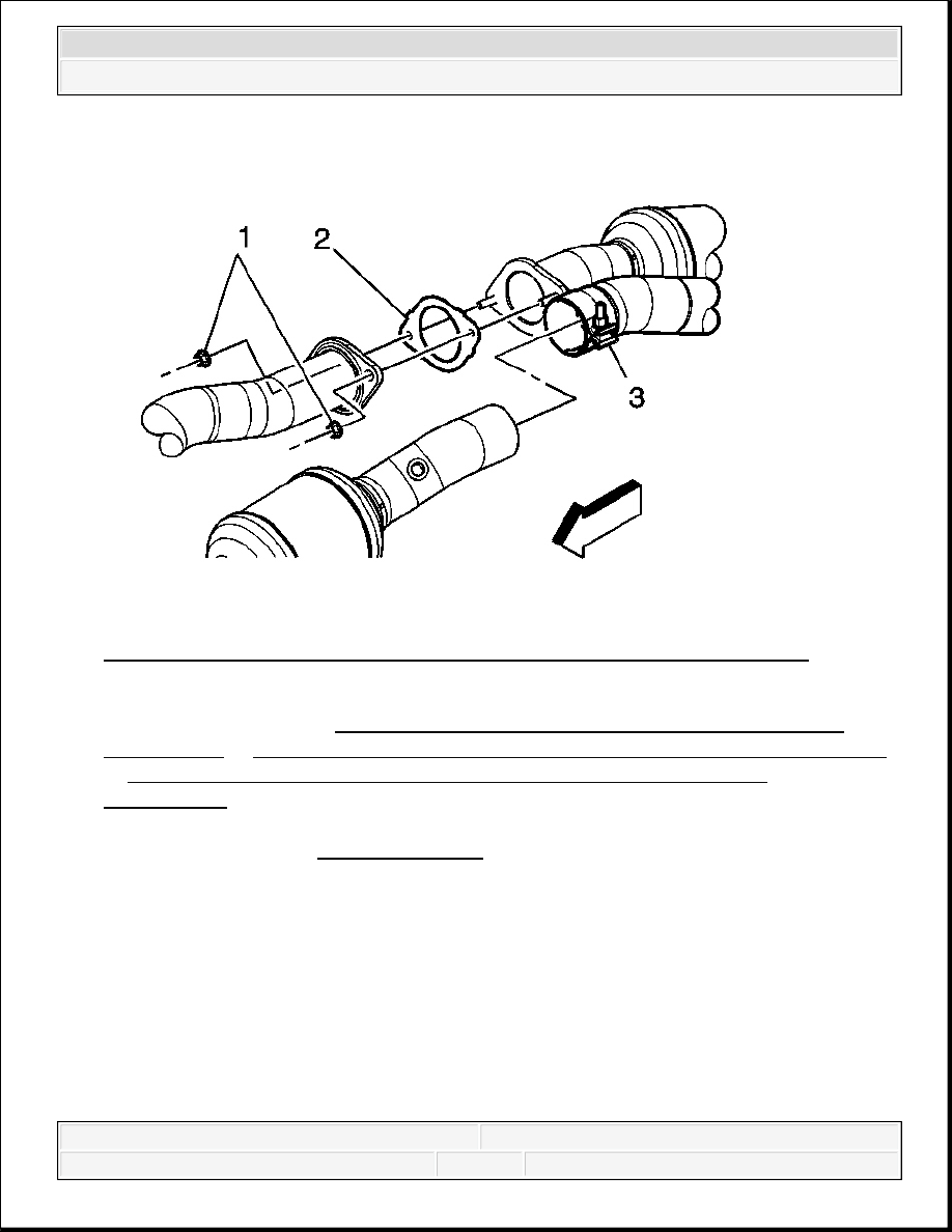
Fig. 210: View Of Exhaust Muffler, Exhaust Manifold Pipe, Gasket & Nuts
Courtesy of GENERAL MOTORS CORP.
4. Install the HO2S. Refer to Heated Oxygen Sensor Replacement - Bank 2 Sensor 2
(1500 Series) or Heated Oxygen Sensor Replacement - Bank 2 Sensor 2 (2500 Series)
or Heated Oxygen Sensor Replacement - Bank 2 Sensor 2 (2500 Series -
Cab/Chassis) .
5. Tighten the exhaust muffler clamp (3).
Tighten: Tighten the nuts to 47 N.m (35 lb ft).
6. Install the exhaust muffler to exhaust manifold pipe nuts (1).
Tighten: Tighten the nuts to 45 N.m (33 lb ft).
NOTE:
Refer to Fastener Notice .
2008 Chevrolet Silverado 1500
2008 ENGINE Engine Exhaust - Cab & Chassis Sierra, Cab & Chassis Silverado, Sierra & Silverado
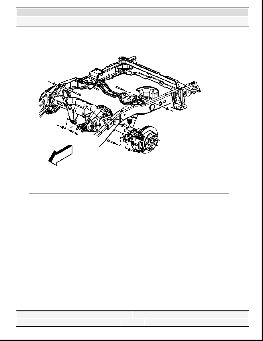
Fig. 211: Rear Shock Absorber Bolts And Nuts (6.0L, 6.6L, and 8.1L Engines)
Courtesy of GENERAL MOTORS CORP.
7. Raise the rear axle using the adjustable jack stands, if necessary.
8. Install the rear shock absorber lower bolts and nuts, if necessary.
Tighten: Tighten the bolts to 95 N.m (70 lb ft).
2008 Chevrolet Silverado 1500
2008 ENGINE Engine Exhaust - Cab & Chassis Sierra, Cab & Chassis Silverado, Sierra & Silverado
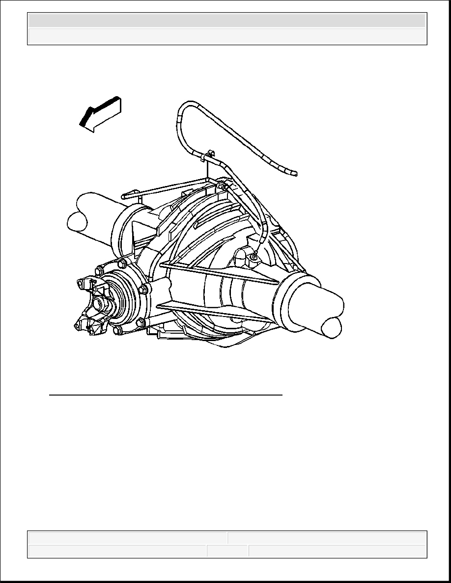
Fig. 212: Rear Axle Vent Hose (10.5 Inch Ring Gear)
Courtesy of GENERAL MOTORS CORP.
9. If equipped with a 10.5 inch ring gear, install the rear axle vent hose to the rear axle, if
necessary.
10. Connect the vent hose swivel clip to the rear brake crossover pipe, if necessary.
2008 Chevrolet Silverado 1500
2008 ENGINE Engine Exhaust - Cab & Chassis Sierra, Cab & Chassis Silverado, Sierra & Silverado
Content .. 1845 1846 1847 1848 ..