Content .. 1660 1661 1662 1663 ..
Chevrolet Silverado / GMC Sierra. Manual - part 1662

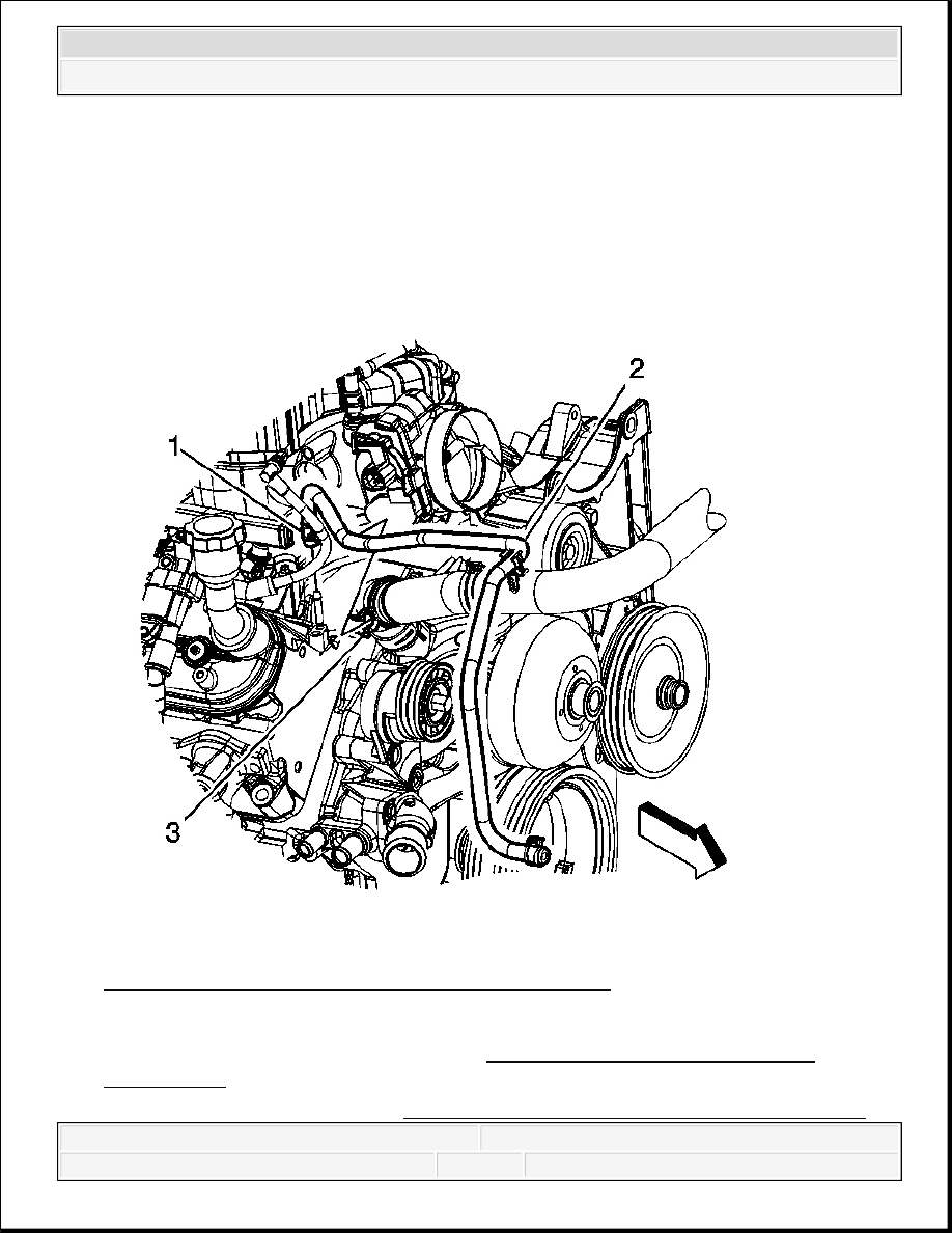
Fig. 190: View Of Fan, Water Pump Pulley & Bolts
Courtesy of GENERAL MOTORS CORP.
4. Using J 41240 , hold the water pump pulley, install the water pump pulley bolts.
Tighten: Tighten the bolts to 25 N.m (18 lb ft).
2008 Chevrolet Silverado 1500
2008 ENGINE Engine Cooling - Cab & Chassis Sierra, Cab & Chassis Silverado, Sierra & Silverado

Fig. 191: View Of Water Pump Inlet Hose & Clamps
Courtesy of GENERAL MOTORS CORP.
5. Install the water pump inlet hose.
6. Position the water pump inlet hose clamps.
IMPORTANT: After assembly, the hose clamp tangs (water pump end) must
point forward and the upper tang should be level with the
outside diameter of the water pump inlet hose.
2008 Chevrolet Silverado 1500
2008 ENGINE Engine Cooling - Cab & Chassis Sierra, Cab & Chassis Silverado, Sierra & Silverado

Fig. 192: View Of Radiator Outlet Hose
Courtesy of GENERAL MOTORS CORP.
7. Install the radiator outlet hose to the water pump.
8. Install the radiator outlet hose to the surge tank.
9. Position the radiator outlet hose clamps at the surge tank and water pump.
10. Install the drive belt. Refer to Drive Belt Replacement .
11. Install the air cleaner outlet duct. Refer to Air Cleaner Outlet Resonator Replacement .
12. Fill the cooling system. Refer to Cooling System Draining and Filling (Vac-N-Fill) or
Cooling System Draining and Filling (Static Fill).
2008 Chevrolet Silverado 1500
2008 ENGINE Engine Cooling - Cab & Chassis Sierra, Cab & Chassis Silverado, Sierra & Silverado
13. Inspect the cooling system for leaks.
WATER PUMP REPLACEMENT (LY6, L76 AND L92)
Removal Procedure
Fig. 193: View Of Radiator Vent Inlet Hose & Clamps
Courtesy of GENERAL MOTORS CORP.
1. Remove the air cleaner outlet duct. Refer to Air Cleaner Resonator Outlet Duct
Replacement .
2. Drain the cooling system. Refer to Cooling System Draining and Filling (Vac-N-Fill) or
2008 Chevrolet Silverado 1500
2008 ENGINE Engine Cooling - Cab & Chassis Sierra, Cab & Chassis Silverado, Sierra & Silverado
Content .. 1660 1661 1662 1663 ..