Content .. 1626 1627 1628 1629 ..
Chevrolet Silverado / GMC Sierra. Manual - part 1628
Tighten: Tighten the nut clockwise to 56 N.m (41 lb ft).
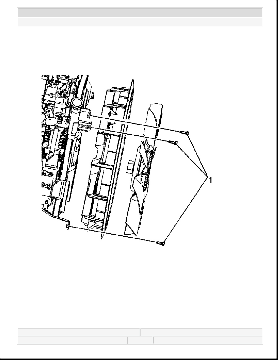
Fig. 59: Identifying Fan Shroud Mounting Brackets & Bolts
Courtesy of GENERAL MOTORS CORP.
5. Position the engine cooling fan shroud on the 3 mounting brackets (1).
6. Install the bolts. Loosely tighten the top mounting bolt at the oil filler neck.
2008 Chevrolet Silverado 1500
2008 ENGINE Engine Cooling - Cab & Chassis Sierra, Cab & Chassis Silverado, Sierra & Silverado
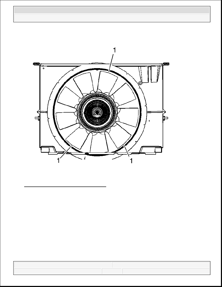
Fig. 60: View Of Cooling Fan Shroud
Courtesy of GENERAL MOTORS CORP.
7. Center the engine cooling fan shroud to the fan blade in 3 places (1).
IMPORTANT: Maintain a 6 mm (0.25 in) minimum clearance at all 3 places.
2008 Chevrolet Silverado 1500
2008 ENGINE Engine Cooling - Cab & Chassis Sierra, Cab & Chassis Silverado, Sierra & Silverado
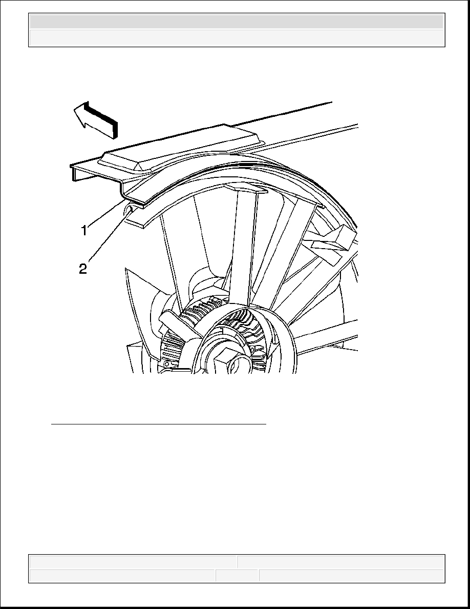
Fig. 61: Cooling Fan Shroud And Rubber Seal
Courtesy of GENERAL MOTORS CORP.
8. Make sure the orientation of the cooling fan shroud (1) and rubber seal (2) are installed
correctly
IMPORTANT: Improper installation could cause damage to the fan and
shroud while vehicle is in service.
2008 Chevrolet Silverado 1500
2008 ENGINE Engine Cooling - Cab & Chassis Sierra, Cab & Chassis Silverado, Sierra & Silverado

Fig. 62: Identifying Fan Shroud Mounting Brackets & Bolts
Courtesy of GENERAL MOTORS CORP.
9. Fully tighten the 3 engine cooling fan shroud bolts (1).
Tighten: Tighten the bolts to 8 N.m (71 lb in).
10. Install the upper fan shroud. Refer to Engine Coolant Fan Upper Shroud Replacement
(Mechanical) or Engine Coolant Fan Upper Shroud Replacement (Automatic
Transmission - Diesel).
2008 Chevrolet Silverado 1500
2008 ENGINE Engine Cooling - Cab & Chassis Sierra, Cab & Chassis Silverado, Sierra & Silverado
Content .. 1626 1627 1628 1629 ..