Chery QQ6 (Body Accessories and Dimensions). Service Manual - part 9
 

  Index      Chery     Chery QQ6 (Body Accessories and Dimensions). Service Manual


Search            copyright infringement  


Content      ..     7      8      9      10     ..


Chery QQ6 (Body Accessories and Dimensions). Service Manual - part 9


129 


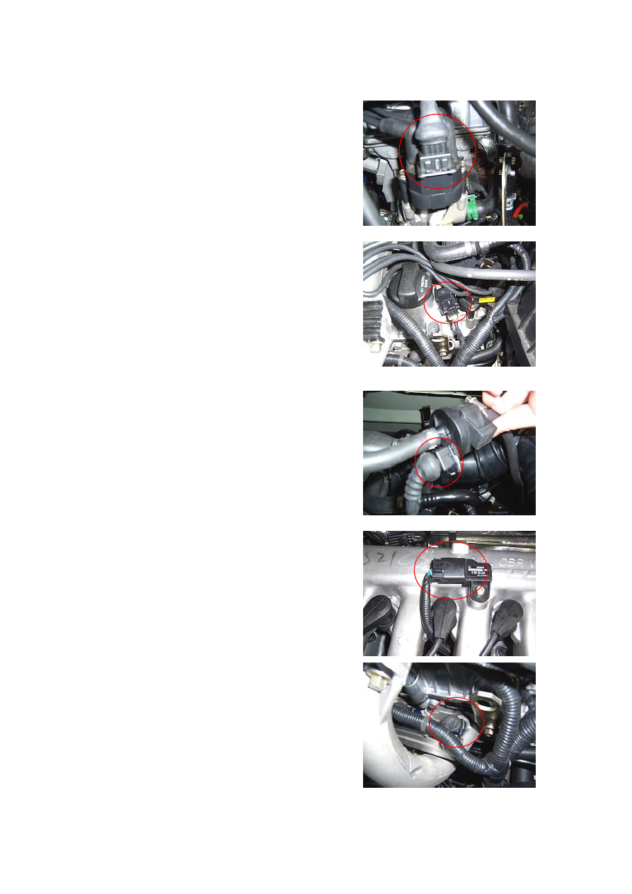
2.1.3. Remove the connectors from the ignition coil. 


2.1.4. Remove the connector from the camshaft sensor.   


2.1.5. Remove the connector from the cansiter solenoid 

valve connector.   


2.1.6.  Remove  the  connector  from  the  air  pressure 

sensor.   


2.1.7.  Remove  four  connectors  from  the  injector 

nozzle. 


-------------------------------------------------------------------------------------------------------------------------------------------------------------

130 


2.1.8.  Remove  the  connector  from  the  charging 

indicator. 


2.1.9. Remove the connector from the generator. 


2.1.10.  Remove  the  starter  connector  and  battery 

connector. 


2.1.11.  Pull  out  the  connector  from  the  A/C 

compressor. 


2.1.12.  Remove  the  connector  from  the  oil  pressure 

switch. 


-------------------------------------------------------------------------------------------------------------------------------------------------------------

131 


2.1.13. Remove the connector from the power steering 

pump. 


2.1.14. Remove the connector from the knock sensor. 


2.1.15.  Remove  the  connector  from  the  backup  lamp 

switch. 


2.1.16.  Remove  the  connector  from  the  water 

temperature sensor. 


2.1.17.  Remove  the  connector  from  the  front  rear 

oxygen sensor.   


-------------------------------------------------------------------------------------------------------------------------------------------------------------

132 


2.1.18.  Remove  the  connector  from  the  vehicle  speed 

sensor.   


2.1.19.  Remove  the  connector  from  the  engine  speed 

sensor. 


2.1.20. Take off the electronic injector harness assy. 


2.2. Installation 

Install it in the reverse order of removal.   


-------------------------------------------------------------------------------------------------------------------------------------------------------------

133 

Section 4    Interior Harness 

I. Schematic Diagram of Harness 

Ground C 

Ground A 

To Back Door Harness 

Rear Left Door Contact Switch 

Rear Left Tail Lamp 

Rear Trunk Lamp 

Rear Left Wheel Sensor 

To Fuel Pump 

To Rear Left Door Harness Connector A 

Rear Right Tail Lamp 

Ground B 

Rear Right Door Contact Switch 

Rear Right Wheel Sensor 

To Rear Left Door Harness Connector B 

To  Front  Left  Door 
Harness Connector A 

To  Front  Left  Door 
Harness Connector B 

To Ceiling Lamp 

Main  Seat 
Belt Switch 

Auxiliary  Seat 
Belt Switch 

Front 

Left 

Door  Contact 
Switch 

Hand Brake Switch 

Window Regulator Module B 

Window Regulator Module A 

Window Regulator Module B 

Window Regulator Module A 

To Engine Compartment Harness 

To  Rear  Right  Door 
Harness Connector B 

To  Rear  Right  Door 
Harness Connector A 

Front 

Right 

Door  Contact 
Switch 

To Instrument Harness Connector A 

To Instrument Harness Connector B 

To Front Right Door Harness 

Ground 

-------------------------------------------------------------------------------------------------------------------------------------------------------------

134 

II. Main Connectors Description 

No 

Connector Description 

Number 

of Pin 

Connection 

Remark 

1 

To front right door harness connector 

16 

Front right door harness 


2 

Right tail lamp connector 

6 

Right tail lamp harness 


3 

Front  right  door  contact  switch 
connector 

1 

Front  right  door  contact 
switch 


4 

To rear right door harness connectorA 

3 

Rear right door harnessA   

5 

To rear right door harness connectorB 

8 

Rear right door harnessB   

6 

Rear right wheel sensor connector 

2 

Rear right wheel sensor 


7 

Rear  right  door  contact  switch 
connector 

1 

Rear  right  door  contact 
switch   


8 

Ground B 

1 

Body 

At  upper  of  rear  right 
wheelhouse paintwork   

9 

To instrument    harness connectorA 

26 

Instrument harness A 


10 

To instrument    harness connectorB 

8 

Instrument harness B 


11 

To  engine  compartment    harness 
connector 

16 

Engine 

compartment 

harness 


12 

To  front  left  door  harness  connector 
B 

8 

Front left door harness B   

13 

To  front  left  door  harness  connector 
A 

16 

Front left door harness A   

14 

Ground A 

1 

Body 

Under left A pillar 

15 

Auxiliary seat belt switch connector 

2 

Auxiliary 

seat 

belt 

switch   


16 

Hand brake switch connector 

1 

Hand brake switch   


17 

Main seat belt switch connector 

2 

Main seat belt switch   


18 

Window  Glass  Regulator  Module  B 
connector 

25 

Window Glass Regulator 
Module B 


19 

Window  Glass  Regulator  Module  A 
connector 

16 

Window Glass Regulator 
Module A 


20 

Ground D 

1 

Body 

At left side  of  window 
regulator module 

21 

Connect to ceiling lamp connector 

2 

Ceiling lamp harness 


22 

Front  left  door  contact  switch 
connector 

1 

Front  left  door  contact 
switch   


23 

To rear left door harness connector B 

8 

Rear left door harness B 


24 

To rear left door harness connector A 

3 

Rear left door harness A 


25 

To fuel pump connector 

4 

Fuel pump harness 


26 

Rear left wheel sensor connector 

2 

Rear left wheel sensor 


27 

Rear 

left 

door 

contact 

switch 

connector 

1 

Rear  left  door  contact 
switch   


28 

Rear trunk lamp connector 

2 

Rear trunk lamp harness 


29 

To back door harness connector 

6 

Back door harness 


30 

Ground C 

1 

Body 

At  rear  paintwork  of 
rear left wheelhouse 

31 

Left tail lampconnector 

6 

Left tail lamp harness 


-------------------------------------------------------------------------------------------------------------------------------------------------------------

135 


III.  Disassembly/Reassembly  of  Interior 
Floor Harness 

Part Number: S21-3724050 

(I). Preparation 

Tools: 

Socket 

wrench, 

cross 

screwdriver, 

flat 

head 

screwdriver 

(II). Precautions 

Power  OFF  before  the  electrical  elements  and 

harnesses are removed. 

The ignition switch must be in OFF state.   

(III). Removal Procedure 

1. Removal of Harness at Left Side of Interior Floor.   

1.1.1.  Remove  the  lower  left  guard  plate  from  the 

instrument  panel.  (See  Disassembly/Reassembly  of 

Instrument Panel) 

1.1.2.  Pull  out  the  connector  to  the  engine 

compartment harness.   


1.1.3.  Pull  out  the  connector  A  to  the  instrument 

harness.   


1.1.4.  Pull  out  the  connector  B  to  the  instrument 

harness. 


-------------------------------------------------------------------------------------------------------------------------------------------------------------

136 


1.1.5.  Remove  the  A  pillar  lower  trim  with  a  cross 

screwdriver.   


1.1.6. Pull  out the connector of  front left  door  harness 

A.   


1.1.7. Pull  out the connector of  front left  door  harness 

B. 


1.1.8. Remove the grounding point. (under the A pillar) 


1.1.9. 

Remove 

the 

console. 

(See 

Disassembly/Reassembly of Console) 

1.1.10.  Remove  the  connector  from  the  hand  brake 

switch. 


-------------------------------------------------------------------------------------------------------------------------------------------------------------

137 


1.1.11.  Remove  the  connector  from  main  seat  belt 

switch. 


1.1.12. 

Remove 

the 

seat 

and 

carpet. 

(See 

Disassembly/Reassembly of Seat and Carpet) 

1.1.13. Pull out two connectors A and B of the window 

regulator.   


1.1.14. Remove the grounding point.   


1.1.15. 

Remove 

the 

B 

pillar 

trim. 

(See 

Disassembly/Reassembly of Seat Belt) 

1.1.16. Remove the front left door contact switch.   


-------------------------------------------------------------------------------------------------------------------------------------------------------------

138 


1.1.17. Pull out the connectors A and B to the right and 

left rear door harnesses.   


1.1.18. 

Remove 

the 

ceiling. 

(See 

Disassembly/Reassembly of Ceiling) 

1.1.19. Pull out the ceiling lampconnector.   


1.1.20. 

Remove 

the 

rear 

seat. 

(See 

Disassembly/Reassembly of Rear Seat) 

1.1.21. Take off the upper protecting cover of oil pump.   


1.1.22. Pull out the connector to the fuel pump.   


1.1.23.  Pull  out  the  connector  of  rear  left  wheel  speed 

sensor. 


-------------------------------------------------------------------------------------------------------------------------------------------------------------

139 


1.1.24. 

Remove 

the 

C 

pillar 

trim. 

(See 

Disassembly/Reassembly of Ceiling) 

1.1.25. Pull out the rear left door contact switch. 


1.1.26. Pull out the connector to the back door harness. 


1.1.27. Pull out the connector of rear trunk lamp. 


1.1.28.  Remove  the  left  grounding  point  from  the 

luggage boot.   


1. 1.29. Remove the connector of left tail lamp.   


1.2 Install it in the reverse order of removal.   


-------------------------------------------------------------------------------------------------------------------------------------------------------------

140 


2. Removal of harness at right side of interior floor.   


2.1.1. 

Remove 

the 

glove 

case. 

(See 

Disassembly/Reassembly of Instrument Panel) 

2.1.2.  Pull  out  the  connector  of  front  right  door 

harness.   


2.1.3.  Remove  the  right  B  pillar  trim.  (See 

Disassembly/Reassembly of Seat Belt) 

2.1.4. Pull out the connector of front right door contact 

switch. 


2.1.5.  Pull  out  the  connectors  A  and  B  of  rear  right 

door harness.   


2.1.6.  Pull  out  the  connector  of  auxiliary  seat  belt 

switch.   


2.1.7. Pull  out the connector of rear right wheel speed 

sensor.   


-------------------------------------------------------------------------------------------------------------------------------------------------------------

141 


2.1.8. 

Remove 

the 

C 

pillar 

trim. 

(See 

Disassembly/Reassembly of Ceiling) 

2.1.9. Pull out the rear right door contact switch.   


2.1.10. Remove the grounding point.   


2.1.11.  Take  off  the  upper  protecting  cover  of  oil 

pump.   


2.1.12. Pull out the connector of right tail lamp.   


2.2. Installation.   

Install it in the reverse order of removal.   


-------------------------------------------------------------------------------------------------------------------------------------------------------------

142 

Section 5    Instrument Harness Assy 

I. Schematic Diagram of Harness 

To Engine Compartment Harness A 

To  Engine  Compartment 
Harness B 

To  Engine  Compartment 
Harness C 

To Interior Harness Connector A    Black 

Self-Diagnostic 

Stop Switch 

Electric  Rear-View 
Mirror Switch 

Combination Instrument 

To Antenna 

To A/C Harness 

Ground A 

Panel Indicator 

Anti-theft Indicator 

Ground B 

Defroster 
Switch 

Cigarette 
Lighter 

Fan Switch 

Alarm Switch 

A/C Switch 

Horn Switch 

Radio 

Air Bag Connector 

Clutch Switch 

Wiper Switch 

(Combination Switch) 

Fog Lamp Switch 

(Combination Switch) 

Turn Signal Dimmer Switch 
(Combination Switch) 


Anti-theft 
Indicator 

Nightlight Switch 

Headlamp Switch 

Ignition Switch 

To Interior Harness Connector B 

Instrument Electrical Box 

Ground C 

-------------------------------------------------------------------------------------------------------------------------------------------------------------

143 

II. Definition of Main Connectors 

Connector 

Pin 

Connect to 

1 

Nightlight Switch   

2 

233(JOINT: Ground or power positive, the same below) 

3 

234(JOINT) 

4 

248(JOINT) 

5 

Combined Instruments 

6 

Wiper Intermittern Relay 

7 

138(JOINT) 

8 

Wiper Switch(combination switch) 

9 

Wiper Switch(combination switch) 

10 

90(JOINT) 

11 

A/C Switch 

12 

Connect to the instrument electrical box   

13 

253(JOINT) 

14 

253(JOINT) 

15 

247(JOINT) 

16 

Turn signal dimmer switch (combination switch) 

17 

Turn signal dimmer switch (combination switch) 

18 

Combined Instruments 

19 

Combined Instruments 

20 

Connect to A/C harness 

21 

Fan Switch 

22 

116(JOINT) 

23 

Connect to A/C harness 

24 

Punch the card at the location near the diagnostic connector 

25 

Brake lamp Switch 

Connect to 

engine 

compartme

nt harness A 

26 

Combined Instruments 

1 

Instrument Electric Device Box 

2 

Ignition Switch 

Connect to 

engine 

compartme

nt harness C 

3 

Instrument Electrical Box f18 

1 

Clutch switch 

2 

Punch the card at the location near the diagnostic connector 

3 

Instrument Electrical Box f13 

4 

9(JOINT) 

5 

Instrument Electrical Box f12 

6 

Combined Instruments 

7 

To Instrument Electrical Box   

8 

Instrument Electrical Box f14 

Connect to 

engine 

compartme

nt harness B 

9 

Instrument Electrical Box f16 

-------------------------------------------------------------------------------------------------------------------------------------------------------------

144 

10 

Combined Instruments 

11 

Combined Instruments 

12 

Combined Instruments 

13 

Combined Instruments 

14 

Combined Instruments 

15 

Combined Instruments 

16 

Instrument Electric Device Box 

1 

271(JOINT) 

2 

Connect to interior harness B 

3 

Connect to interior harness B 

4 

Connect to interior harness B 

5 

Connect to interior harness B 

6 

Connect to interior harness B 

7 

138(JOINT) 

8 

302(JOINT) 

9 

—— 

Electric 

Rearview 

Mirror 

Switch 

10 

—— 

1 

Audio device 

2 

Audio device 

3 

140(JOINT) 

4 

Combined Instruments 

5 

Combined Instruments 

6 

Combined Instruments 

7 

Combined Instruments 

8 

9(JOINT) 

9 

Instrument Electric Device Box 

10 

Instrument Electrical Box f18 

11 

142(JOINT) 

12 

Anti-theft indicator   

13 

—— 

14 

Audio device 

15 

Audio device 

16 

Audio device 

17 

Audio device 

18 

271(JOINT) 

19 

Instrument Electrical Box f17 

20 

Audio device 

21 

Audio device 

22 

Defroster Switch; 

23 

234(JOINT) 

24 

233(JOINT) 

25 

90(JOINT) 

Connect to 

the interior 

harness 

connectorA 

(black) 

26 

—— 

-------------------------------------------------------------------------------------------------------------------------------------------------------------


Content      ..     7      8      9      10     ..