Chery Tiggo 5 (T21). Manual - part 484


  Index      Chery     Chery Tiggo 5 (T21) - service repair manual 2014 year


Search            


Content   ..  482  483  484  485   ..


Chery Tiggo 5 (T21). Manual - part 484


45–

14

45

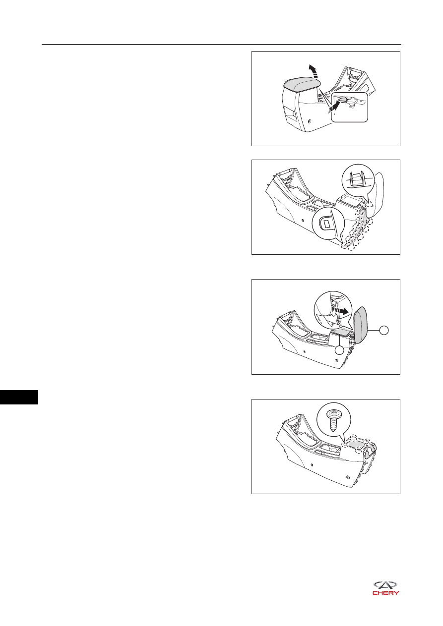
b. Open the armrest box cover assembly in the direction 

of arrow as shown in the illustration.

c. Using a screwdriver wrapped with protective tape, pry 

up the claws on auxiliary fascia console rear cover 
plate assembly.

d. Remove the auxiliary fascia console rear cover plate 

assembly from auxiliary fascia console assembly.

3. Remove the armrest box cover assembly and armrest inner storage box.

a. Pull out the hinge shaft in the direction of arrow as 

shown in the illustration.

b. Remove the armrest box cover assembly (1) and 

armrest inner storage box (2) from auxiliary fascia 
console assembly.

4. Remove the armrest box assembly.

a. Remove 4 fixing screws from armrest box assembly.

(Tightening torque: 1.5 ± 0.5 N·m)

b. Remove the armrest box assembly from auxiliary 

fascia console assembly.

RT21450200

RT21450210

1

2

RT21450220

RT21450230

45–

15

45

5. Remove the cup holder assembly.

a. Remove 9 fixing screws from cup holder assembly.

(Tightening torque: 1.5 ± 0.5 N·m)

b. Remove the cup holder assembly from auxiliary fascia 

console assembly.

6. Remove the auxiliary fascia console front trim ring.

a. Remove 10 fixing screws from auxiliary fascia console 

front trim ring.

(Tightening torque: 1.5 ± 0.5 N·m)

b. Remove the auxiliary fascia console front trim ring 

from auxiliary fascia console assembly.

7. Remove the auxiliary fascia console front inner protector assembly.

a. Remove the auxiliary fascia console front inner 

protector assembly from auxiliary fascia console 
assembly.

8. Remove the gear backlight.

a. Remove 2 fixing screws (1) from gear backlight.

(Tightening torque: 1.5 ± 0.5 N·m)

b. Using a screwdriver wrapped with protective tape, 

disengage the claws (arrow).

c. Remove the gear backlight from gearshift cover plate.

9. Remove the cigarette lighter assembly (

See page 42-5

).

10.Remove the backup power supply assembly (

See page 42-7

).

RT21450240

RT21450250

RT21450260

RT21450270

1

1

45–

16

45

11.Remove the multifunctional interface.

a. Press the claws (arrow) on multifunctional interface as 

shown in the illustration.

b. Remove the multifunctional interface from USB panel 

assembly.

Assembly

Assembly is in the reverse order of disassembly.

Installation

Installation is in the reverse order of removal.

iPod

AUX

RT21450280

iPod

AUX

CAUTION

 Make sure to tighten fixing bolts and fixing screws to the specified torque when installing auxiliary fascia 

console assembly.

 Check each electrical equipment for proper operation after installing auxiliary fascia console assembly.

45–

17

45

Instrument Panel Assembly

Removal

1. Turn off all the electrical equipment and ignition switch.
2. Disconnect the negative battery cable.
3. Remove the glove box assembly.

a. Open the glove box assembly in the direction of arrow 

as shown in the illustration.

b. Rotate the lock knobs (arrow) clockwise, and remove 

the lock knobs.

WARNING

 Wait at least 60 seconds after disconnecting negative battery cable to disable supplementary restraint 

system. 

 When removing and installing instrument panel assembly, all components related to airbag should be 

operated with battery power source off. It is forbidden to operate them with power source on. Because 
within 60 seconds after vehicle stops or fuse removed, there is enough power inside the airbag control 
module for activating the airbag, and the airbag can be accidentally activated, causing personal injury or 
vehicle damage.

 DO NOT expose airbag components to hot air or flame. 
 Removed airbag should be well kept. If triggered accidentally, the airbag may cause personal injury.

CAUTION

 Be sure to wear safety equipment to prevent accidents when removing instrument panel assembly.
 DO NOT scratch interior and body paint when removing instrument panel assembly.

RT21450281

RT21450282


Content   ..  482  483  484  485   ..