Chery Tiggo 5 (T21). Manual - part 209


  Index      Chery     Chery Tiggo 5 (T21) - service repair manual 2014 year


Search            


Content   ..  207  208  209  210   ..


Chery Tiggo 5 (T21). Manual - part 209


18–

25

18

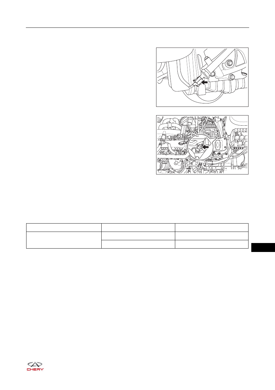
Primary/Secondary Shaft Pressure Sensor Inspection

1. Turn off all the electrical devices and ignition switch.
2. Disconnect the primary/secondary shaft pressure sensor 

connector.

3. Check for resistance between the terminals of primary/secondary shaft pressure sensor as shown in the 

table below at normal temperature.

HINT:
The inner parts of the sensor are triode and capacitor, and will be affected greatly by the environment and the 
usage condition. Therefore, the actual measured value is within the specified value plus/minus 15% in the 
table below.

RT21180280

RT21180290

Item

Multimeter Connection

Specified Condition (KΩ)

Primary/Secondary Shaft Pressure 

Sensor

1 - 3

45.77

2 - 1

10.06

18–

26

18

Problem Symptoms Table

HINT:
Use the table below to help determine the cause of problem symptoms. Check each suspected area in 
sequence. Repair or replace the faulty components, or adjust as necessary.

Diagnostic Help

1. Connect X-431 3G diagnostic tester (the latest software) to Data Link Connector (DLC), and make it 

communicate with vehicle electronic module by the data network.

2. Confirm that the malfunction occurs, and perform diagnosis tests and repair procedures.
3. If diagnostic trouble code (DTC) cannot be deleted, it is a current malfunction.
4. Only use a digital multimeter to measure the voltage of electrical systems. 
5. Refer to any Technical Bulletin that may apply to the malfunction. 
6. Visually check the related wire harnesses. 
7. Inspect and clean all engine control module (ECM) grounds that are related to the latest DTC.
8. If multiple trouble codes were set, use the circuit diagrams and look for any common ground circuit or 

power supply circuit applied to the DTC.

Symptoms

Suspected Area

See page

With power-on or ignited, P gear is not 
released after applying brake

Brake switch or circuit 

26-26

Gear shift lock solenoid 

-

High impact during static gear shifting

Turbine speed sensor 

18-116

Circuit or connector 

-

Solenoid 

-

Vehicle fails to move when D/R gear is 
engaged, or engaged gear is different from 
gear shown in the instrument

Gear shift cable and transmission shift arm 
(assembled incorrectly)

18-127

Variable speed anomaly, jumbled speed 
shifting in driving; abnormal driving and 
poor comfort

Oil pressure switch 

13-16

Circuit or connector 

-

Speed sensor 

06-249

Vehicle fails to run after gear is engaged, 
but gear indication is normal 

Transmission fluid pump 

-

Solenoid 

-

Vehicle fails to run when reverse gear is 
engaged

Transmission planetary gear system 

-

Vehicle stalls when D/R gear is engaged

Radiator oil pipes (incorrectly assembled, 
bent or folded)

12-29

Locking clutch (abnormal)

-

Abnormal noise of transmission in 
acceleration

Transmission fluid (insufficient)

18-110

Reduced power and speed in high 
speeding driving

Thermal protection of transmission

-

18–

27

18

Intermittent DTC Troubleshooting

If malfunction is intermittent, perform the followings:
 Check if connectors are loose.
 Check if wire harnesses are worn, pierced, pinched or partially broken.
 Wiggle related wire harnesses and connectors and observe if signal is interrupted in the related circuit.
 If possible, try to duplicate the conditions under which the DTC was set.
 Look for the data that has changed or the DTC to reset during the wiggle test.
 Look for broken, bent, protruded or corroded terminals.
 Inspect the mounting areas of instrument cluster, wire harness or wire harness connector and so on for 

damage, foreign matter, etc. that will cause incorrect signals. 

Ground Inspection

Groundings are very important to entire circuit system, which are normal or not can seriously affect the entire 
circuit system. Ground points are often exposed to moisture, dirt and other corrosive environments. Corrosion 
(rust) and oxidation can increase load resistance. This situation will seriously affect the normal operation of 
the circuit. The operations to check the ground points are as follows:
1. Remove the ground bolt or nut.
2. Check all contact surfaces for tarnish, dirt and rust, etc.
3. Clean as necessary to ensure that contacting is in a good condition.
4. Reinstall the ground bolt or nut securely.
5. Check if add-on accessories interfere with the ground circuit.
6. If several wire harnesses are crimped into one ground eyelet terminal, check if they are installed correctly. 

Make sure all wire harnesses are clean, securely fastened and providing a good ground path.

Diagnostic Trouble Code (DTC) Chart

DTC Code

DTC Definition

P1700

Unexpected Interrupt 

P0700

Transmission Control System (MIL Request)

P0701

Transmission Control System Performance 

P0702

Transmission Control System Electrical

P0703

Brake Switch 'B' Circuit

P0705

Transmission Range Sensor 'A' Circuit (PRNDL Input)

P0706

Transmission Range Sensor 'A' Circuit Range (PRNDL Input)

P0707

Transmission Range Sensor 'A' Circuit Low (PRNDL Input)

P0708

Transmission Range Sensor 'A' Circuit High (PRNDL Input)

P0709

Transmission Range Sensor 'A' Circuit Intermittent (PRNDL Input)

P0715

Input/Turbine Speed Sensor Circuit 

P0716

Input/Turbine Speed Sensor Circuit Range 

P0717

Input/Turbine Speed Sensor Circuit No Signal 

P0718

Input/Turbine Speed Sensor Circuit Intermittent

P0719

Brake Switch 'B' Circuit Low 

P071A

Transmission Sport Mode Switch Circuit 

18–

28

18

P071B

Transmission Sport Mode Switch Circuit Low 

P071C

Transmission Sport Mode Switch Circuit High 

P071D

Transmission Winter Mode Switch Circuit 

P071E

Transmission Winter Mode Switch Circuit Low

P071F

Transmission Winter Mode Switch Circuit High

P0720

Output Speed Sensor Circuit 

P0721

Output Speed Sensor Circuit Range/Performance 

P0722

Output Speed Sensor Circuit No Signal

P0723

Output Speed Sensor Circuit Intermittent

P0724

Brake Switch 'B' Circuit High 

P0725

Engine Speed Input Circuit 

P0726

Engine Speed Input Circuit Range/Performance

P0727

Engine Speed Input Circuit No Signal 

P0728

Engine Speed Input Circuit Intermittent

P0730

Incorrect Gear Ratio 

P0740

Torque Converter Clutch Circuit Open 

P0741

Torque Converter Clutch Circuit Performance

P0742

Torque Converter Clutch Circuit Stuck On 

P0743

Torque Converter Clutch Circuit Electrical

P0744

Torque Converter Clutch Circuit Intermittent

P0745

Pressure Control Solenoid 'A' 

P0746

Pressure Control Solenoid 'A' Stuck Off 

P0747

Pressure Control Solenoid 'A' Stuck On 

P0748

Pressure Control Solenoid 'A' Electrical

P0749

Pressure Control Solenoid 'A' Intermittent

P0775

Pressure Control Solenoid 'B' 

P0776

Pressure Control Solenoid 'B' Stuck Off 

P0777

Pressure Control Solenoid 'B' Stuck On 

P0778

Pressure Control Solenoid 'B' Electrical 

P0779

Pressure Control Solenoid 'B' Intermittent

P0791

Intermediate Shaft Speed Sensor 'A' Circuit

P0792

Intermediate Shaft Speed Sensor 'A' Circuit Range

P0793

Intermediate Shaft Speed Sensor 'A' Circuit No Signal

P0794

Intermediate Shaft Speed Sensor 'A' Circuit Intermittent 

P0811

Drive Clutch 'A' Slippage 

P0814

Transmission Range Display Circuit 

P0815

Upshift Switch Circuit 

DTC Code

DTC Definition


Content   ..  207  208  209  210   ..