Chery Tiggo 5 (T21). Manual - part 208


  Index      Chery     Chery Tiggo 5 (T21) - service repair manual 2014 year


Search            


Content   ..  206  207  208  209   ..


Chery Tiggo 5 (T21). Manual - part 208


18–

21

18

DIAGNOSIS & TESTING

Transmission Fluid Level and Quality Inspection

1. After the vehicle runs for 5 min, the temperature will reach the normal working conditions (ATF temperature 

60 - 80°C, and the engine coolant temperature 80 - 100°C).

2. Park the vehicle on a flat ground and pull the parking brake lever.
3. Start up the engine to make it run at idle speed, and then fully depress the brake pedal and move the shift 

lever for five times at each gear. Finally, place the lever at "P" or "N" position.

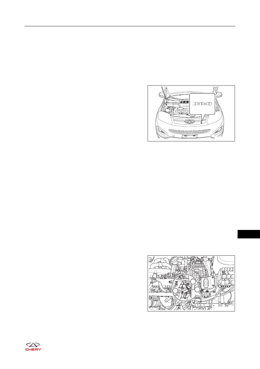
4. Pull out the automatic transmission fluid dipstick and 

clean it with non-wool paper; then insert the dipstick into 
the filling pipe as much as possible and then take out to 
observe whether it reaches the "HOT" position.

5. Check the transmission fluid:
 If the fluid becomes brown, replace the automatic transmission fluid and check the vehicle for working 

conditions. 

 If the fluid becomes milk white or cloudy, or there is water in the fluid, replace the automatic transmission 

fluid and check for the leaking location. 

 If the fluid becomes black with a lot of powders and there is abnormal wear in the CVT, replace the 

automatic transmission fluid and check the vehicle for normal working.

Gear Shift Cable Inspection and Adjustment

Shift the gear lever from "N" gear to other gears to check whether the lever can be shifted to other gears 
smoothly and precisely, and also check whether the gear indicators can indicate the gear correctly.
If the gear indicators indicate incorrectly, adjust them as shown below:
1. Park the vehicle at a safe place and pull the parking brake lever. 
2. Change the shift lever to the "N" position.
3. Turn off all the electrical devices and ignition switch.
4. Disconnect the negative battery cable.
5. Remove the battery, battery tray and tray bracket (

See page 16-7

).

6. Remove the connecting nut (3) of the gear shift cable (1) 

and shift arm (2). Disconnect the gear shift cable from the 
shift arm.

RT21180200

RT21180210

1

3

2

18–

22

18

7. Loosen the transmission range sensor fixing bolts, and 

adjust the relative position of the transmission range 
sensor and shift arm to make the holes of gear shift arm 
(1) and transmission range sensor (2) coincident.

8. Use a proper tool to fix the gear shift arm and transmission range sensor, and then tighten the bolts to the 

specified torque.

9. Start engine only when the gear lever is at the "P" or "N" gear.

Transmission Range Sensor Inspection

1. Turn off all the electrical devices and ignition switch.
2. Disconnect the negative battery cable.
3. Disconnect the transmission range sensor wire harness 

connector.

4. Check for continuity between the terminals of transmission range sensor wire harness connector 

according to the table below.

If result is not as specified, replace the transmission range sensor.

RT21180220

1

2

CAUTION

 The ledge of the gear shift cable must be placed into the slot of shift arm.

RT21180230

Gearshift Position

Terminal

Specified Condition

P

1 - 7, 9 - 10

Continuity

R

7 - 8

N

2 - 7, 9 - 10

D

3 - 7

L

4 - 7

18–

23

18

Transmission Fluid Temperature Sensor Inspection

1. Turn off all the electrical devices and ignition switch.
2. Disconnect the transmission wire harness connector.
3. Check for resistance between the transmission wire 

harness connector terminals 1 and 2.

Primary Shaft Speed Sensor Inspection

1. Turn off all the electrical devices and ignition switch.
2. Disconnect the primary shaft speed sensor connector.
3. Check for resistance between the terminals of primary 

shaft speed sensor as shown in the table below at normal 
temperature.

HINT:
The inner parts of the sensor are triode and capacitor, and will be affected greatly by the environment and 
usage condition. Therefore, the actual measured value is within the specified value plus/minus 15% in the 
table below.

RT21180240

Item

Terminal

Temperature (°C (°F)) 

Resistance (KΩ)

Gear Box

1 - 2

20 (68)

6.5

80 (176)

0.9

RT21180250

Item

Multimeter Connection

Specified Condition 

(MΩ)

Primary Shaft Speed Sensor

+

-

1

3

3.313

3

1

6.56

1

2

1.649

3

2

11.56

18–

24

18

Turbine/Secondary Shaft Speed Sensor Inspection

1. Turn off all the electrical devices and ignition switch.
2. Disconnect the turbine/secondary shaft speed sensor 

connector.

3. Check for resistance between the terminals of turbine/secondary shaft speed sensor as shown in the table 

below at normal temperature.

HINT:
The inner parts of the sensor are triode and capacitor, and will be affected greatly by the environment and 
usage condition. Therefore, the actual measured value is within the specified value plus/minus 15% in the 
table below.

RT21180260

RT21180270

Item

Multimeter Connection

Specified Condition 

(MΩ)

Turbine/Secondary Shaft Speed 

Sensor

+

-

1

3

3.397

3

1

6.79

1

2

1.77

3

2

11.9


Content   ..  206  207  208  209   ..