Chery Tiggo 5 (T21). Manual - part 204


  Index      Chery     Chery Tiggo 5 (T21) - service repair manual 2014 year


Search            


Content   ..  202  203  204  205   ..


Chery Tiggo 5 (T21). Manual - part 204


18–

5

18

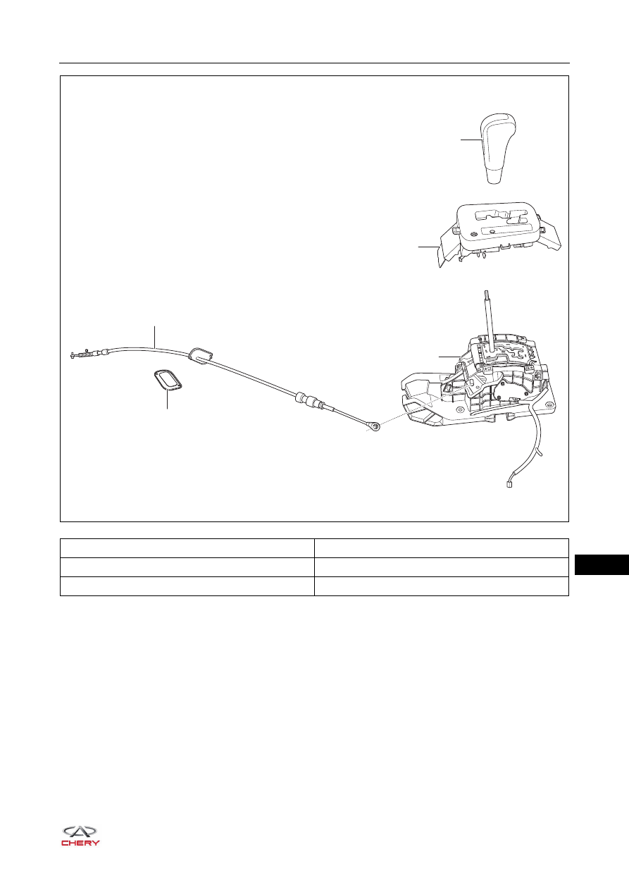
1 - Gear Shift Cable

2 - Gear Shift Lever Knob

3 - Gear Indicator Panel

4 - Gear Shift Control Mechanism

5 - Gear Shift Cable Dust Boot

2

3

4

5

1

RT21180020

18–

6

18

1 - Turbine Speed Sensor

2 - Secondary Shaft Speed Sensor

3 - Secondary Shaft Pressure Sensor

4 - Primary Shaft Speed Sensor

5 - Primary Shaft Pressure Sensor

6 - Transmission Range Sensor

3

4

5

1

2

6

RT21180030

18–

7

18

Precautions

1. During removal and installation, make sure that the gear shift lever is at "N" position.
2. When installing the gear shift arm and transmission range sensor, use a proper tool to fix them, and then 

tighten bolts to the specified torque.

3. The components of transmission are of high precision, so take care in removal and installation and do not 

scratch or damage any component.

4. When installing the oil seal, apply force evenly and do not cause deformation or damage of oil seal.
5. Keep transmission components clean when removing and installing transmission components to prevent 

foreign matter from entering the transmission.

6. When installing the torque converter onto transmission, make sure that the oil pump drive slot is installed in 

place; otherwise it will cause abnormal damage to the transmission.

7. When assembling engine and transmission, make sure that the four connecting bolts of engine flywheel 

and torque converter are not ignored.

8. When assembling engine and transmission, make sure that all connecting bolts are installed correctly and 

completely, and the torques meet the specifications.

9. When disassembling and assembling engine and transmission, make sure that the torque converter does 

not drop down.

10.When assembling engine and transmission, make sure that the dust baffle is not ignored.
11.When replacing transmission sensors and oil seals, make sure that they are installed in place and bolt 

torques meet the specifications.

12.Take measures to avoid foreign matter entering the transmission, when removing or installing the cooling 

oil pipes and radiator. And check the fluid level and make sure that there is no leakage after installation.

Operation

Speed Ratio Change Principle

The CVT uses a metal belt and V-shape drive and driven pulleys with width-variable slot for the power 
transition. The drive and driven pulleys consist of movable and fixed discs. The pulley close to the oil cylinder 
could slide on the pulley shaft and the one on other side is fixed. The movable and fixed discs are of cone 
structure. Their cones form a V-shape slot for engagement of the V-shape metal belt. It changes the working 
radius of the engagement of the cones and V-shape metal belt to shift the speed by the axial movement of the 
movable disc when working.
Right illustration shows the low speed ratio:
1. Input pulley
2. Output pulley
3. Input circle
4. Output circle

2

1

3

4

V-belt

Clamping 

Low

Low speed ratio

Transmission

pressure

oil

pressure oil

oil passage

RT21180040

18–

8

18

Right illustration shows the high speed ratio:
1. Input pulley
2. Output pulley
3. Input circle
4. Output circle

Torque Converter

The torque converter is used to keep stable start, reduce torsional vibration of transmission system and 
prevent overload of the transmission system.
The torque converter could ensure stable start and even 
acceleration of the vehicle. The hydraulic vibration 
absorption could eliminate or reduce the impact and 
dynamic load in the transmission system, extending the 
service life of the components of the engine and 
transmission system.

Transmission Control Unit (TCU)

The transmission control unit (TCU) is installed on the 
battery tray. It receives input signals of switches and sensors 
and mainly controls the operation of the gear shifting and 
locking solenoid. Transmission gears are regulated by the 
electronic gear shift system. The TCU processes the input 
signals and regulates transmission hydraulic system by 
exploiting the information received.

V-belt

Clamping 

High 

High speed ratio

Transmission

2

1

3

4

pressure

oil

pressure oil

oil passage

RT21180050

1

2

3

4

5

8

7

6

RT21180060

1 - Pump Wheel

2 - Turbine

3 - Front Case

4 - Bearing

5 - Guide Wheel and 

One-way Clutch

6 - Clutch Assembly

7 - Welded Hub

8 - Drive Hub

RT21180070


Content   ..  202  203  204  205   ..