Chery Tiggo 5 (T21). Manual - part 125


  Index      Chery     Chery Tiggo 5 (T21) - service repair manual 2014 year


Search            


Content   ..  123  124  125  126   ..


Chery Tiggo 5 (T21). Manual - part 125


07–

86

07

40.Remove the crankshaft main bearing shell.

a. Slightly push the crankshaft main bearing upper shell 

(1) in the direction of arrow and remove it carefully.

HINT:

 Remove other crankshaft main bearing upper 

shells from the cylinder block in the same way.

 Remove the crankshaft main bearing lower shells 

from the crankshaft frame in the same way. 

 Pay attention to the notch position. Push out the 

bearing shell carefully as shown in the illustration. 
It is difficult to push out the bearing shell and the 
parts may be damaged if pushing in the opposite 
direction.

Inspection

1. Check cylinder block.

Clean engine block thoroughly and check all hole passages for leakage. 
Check engine block and cylinder bore for cracks. 
Check bottom surface of engine block for cracks.

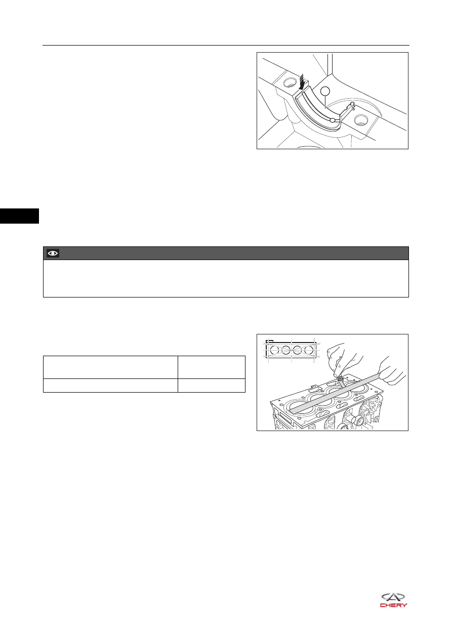
2.  Check flatness of engine block upper surface. 

a. Clean the engine block upper surface. 
b. Using a precision ruler and feeler gauge, measure the 

flatness of engine block upper surface. 

It is not allowed to grind the block upper surface. If the 
flatness of engine block upper surface exceeds the 
limit, replace the engine block.

3. Check cylinder.

a. Cylinder cylindricity and roundness calculation method (for general measurement): 

Thrust direction - perpendicular to the axis of crankshaft; Axial direction: Parallel with the axis of 
crankshaft
Cylindricity calculation method 
Cylindricity is half of the diameter difference measured in the same direction. 
Cylindricity in thrust direction = (maximum diameter measured at A, B and C in thrust direction - 
minimum diameter measured at A, B and C in thrust direction)/2
Cylindricity in axial direction = (maximum bore diameter measured at A, B and C in axial direction - 
minimum bore diameter measured at A, B and C in axial direction)/2
Compare the maximum value measured at the 2 directions with the standard cylinder cylindricity.
Roundness calculation method 

1

RT21071020

CAUTION

 DO NOT wash the cylinder at high temperature. Otherwise the cylinder liner will stick out beyond the 

engine block. 

RT21071030

Measurement Item

Specification 

(mm)

Engine Block Upper Surface Flatness

0.04

07–

87

07

Roundness error is half of the diameter difference measured at the same section. 
Roundness of Section A = (maximum bore diameter measured in thrust direction and axial direction at 
point A - minimum bore diameter measured in thrust direction and axial direction at point A)/2
Roundness of Section B = (maximum bore diameter measured in thrust direction and axial direction at 
point B - minimum bore diameter measured in thrust direction and axial direction at point B)/2 
Roundness of Section C = (maximum bore diameter measured in thrust direction and axial direction at 
point C - minimum bore diameter measured in thrust direction and axial direction at point B)/2
Compare maximum value roundness measured at A, B and C with the standard cylinder roundness.

b. Check cylindricity of cylinder.

Using a cylinder gauge, measure the cylinder bore at 
positions A, B and C in the thrust and axial directions.

If the cylindricity or roundness value measured at 
positions A, B and C exceeds the specified value, 
replace the engine block. 

4. Check piston. 

a. Using a scraper, remove the carbon deposits on the 

top of piston.

b. Using a piston ring, remove the carbon deposits in the 

piston ring groove.

Front

12 mm

C

B

A

Center

Axial Direction

Thrust Direction

12 mm

RT21071040

Measurement Item

Specification 

(mm)

Cylinder Cylindricity

0.01

Cylinder Roundness

0.008

RT21071050

RT21071060

07–

88

07

c. Using a brush and solvent, thoroughly clean the 

piston. 

d. Measure the piston diameter with a micrometer at the 

position that is approximately 11 mm under the piston 
skirt in the vertical direction of piston pin.

If piston diameter is not within the specified range, 
replace the piston connecting rod assembly. 

5. Check clearance between piston ring and ring groove 

side.
Using a feeler gauge, measure the clearance between 
new piston ring and ring groove side.

If piston ring side clearance is not within the specified 
range, replace the piston connecting rod assembly.

RT21071070

CAUTION

 DO NOT use a wire brush to clean.

11 mm

RT21071080

Measurement Item

Specification 

(mm)

Piston Diameter 

83.455 ± 0.009

RT21071090

Measurement Item

Specification 

(mm)

Piston Ring Side 

Clearance

First Ring

0.04 - 0.08

Second Ring

0.025 - 0.070

07–

89

07

6. Check piston ring end gap.

a. Using a piston, push the piston ring from the top of 

cylinder to a place that is 45 mm from the top of 
cylinder bore.

b. Using a feeler gauge, measure the end gap.

If piston ring end gap is not within the specified range, 
replace the piston ring with a new one. 
If end gap is still not within the specified range after 
replacement, replace the engine block. 

7. Check diameter of crankshaft main journal.

a. Using a micrometer, measure the main journal 

diameter. Measure again after rotating the crankshaft 
for 90°.

If crankshaft main journal diameter is not within the 
specified range, replace the main bearing shells with 
new ones, and check radial clearance of crankshaft 
(

See page 07-90

). 

If radial clearance of the main bearing shell is still not 
within the specified range after replacement, replace 
the crankshaft. 

b. Calculate the crankshaft cylindricity by measured values (measured area is shown in the illustration).

Roundness calculation method (for general measurement): 
Measure the diameter twice on the same cross section, and the roundness is half of the difference 
between maximum and minimum values. 
Roundness = (maximum diameter - minimum diameter)/2
As shown in the illustration, measure the diameter twice in different directions on two cross sections 
separately to obtain four values. The cylindricity is the half of the difference between maximum and 
minimum values among the four values. 
Cylindricity = (maximum diameter - minimum diameter)/2

45 mm

RT21071100

Measurement Item

Specification 

(mm)

Piston Ring End 

Gap

First Ring

0.2 - 0.4

Second Ring

0.4 - 0.6

RT21071110

Measurement Item

Specification 

(mm)

Crankshaft Main Journal Diameter 

54

  0
 -0.019

Measurement Item

Specification (mm)

Crankshaft Main Journal

Cylindricity

0.007

Roundness

0.04


Content   ..  123  124  125  126   ..