Chery Tiggo 5 (T21). Manual - part 123
07–
78
07
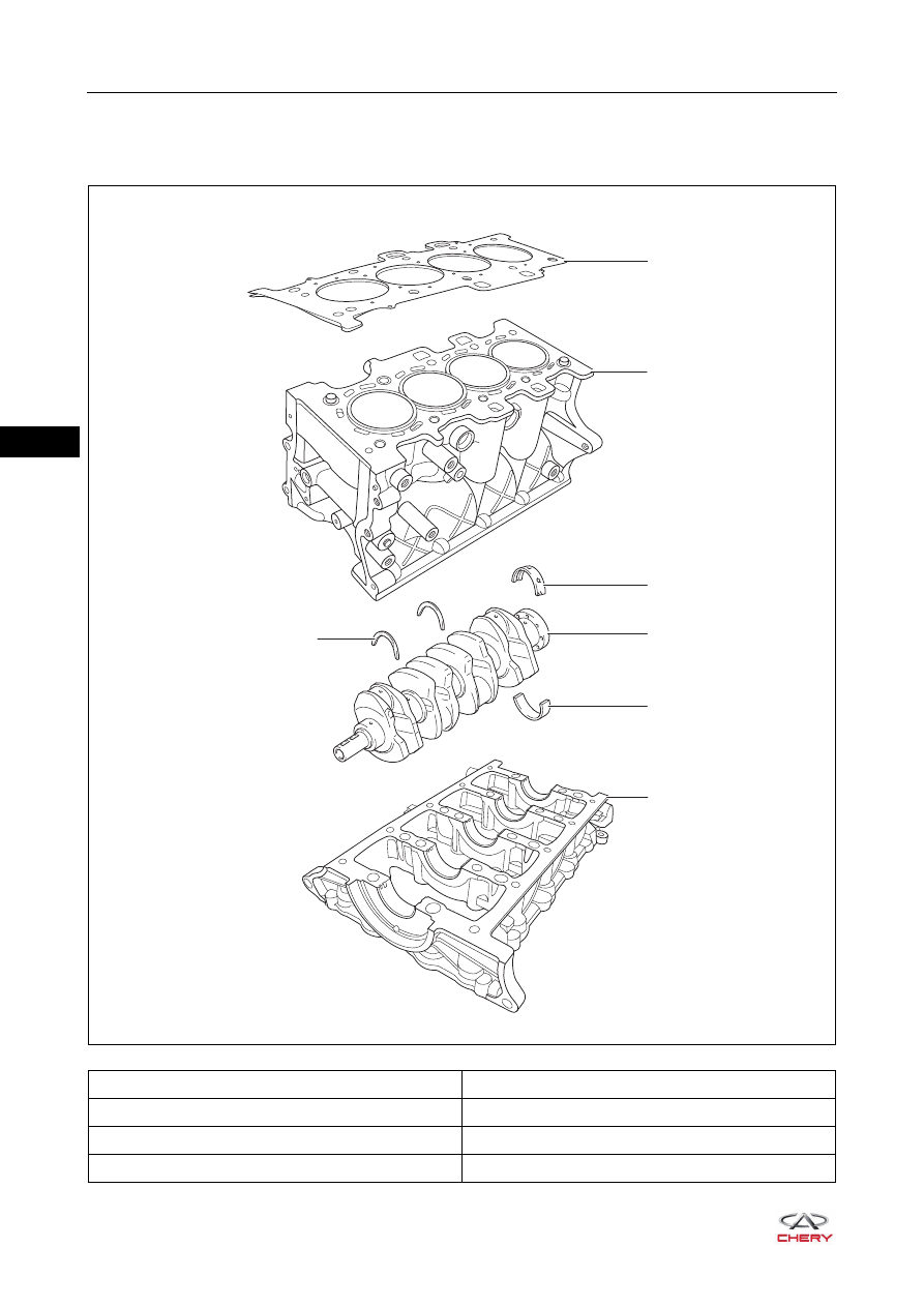
Engine Block
Description
1 - Cylinder Head Gasket
2 - Cylinder Block
3 - Crankshaft Main Bearing Upper Shell
4 - Thrust Washer
5 - Crankshaft
6 - Crankshaft Main Bearing Lower Shell
7 - Crankshaft Frame
RT21070860
3
5
6
7
2
1
4