Chery Tiggo. Manual - part 427
B3042 - W-Line Short Circuit To Ground
B3043 - W-Line Short Circuit To Battery
Immobilizer Control Module
DIAGNOSIS & TESTING
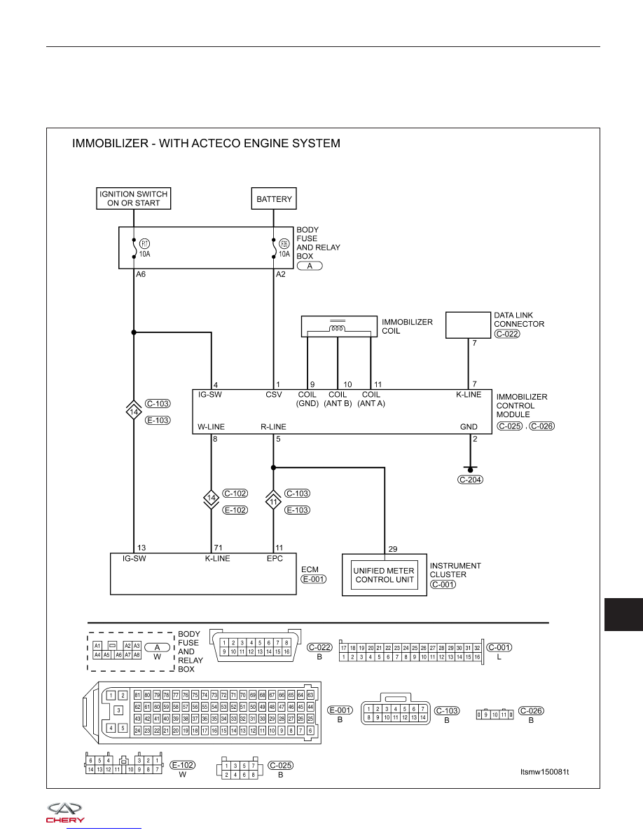
LTSMW150081T
15
|
|
|
B3042 - W-Line Short Circuit To Ground Immobilizer Control Module DIAGNOSIS & TESTING LTSMW150081T 15
|