Chery Tiggo. Manual - part 426
Diagnostic Trouble Code (DTC) Tests
B1000 - ECU Defect: Internal Errors
DIAGNOSIS & TESTING
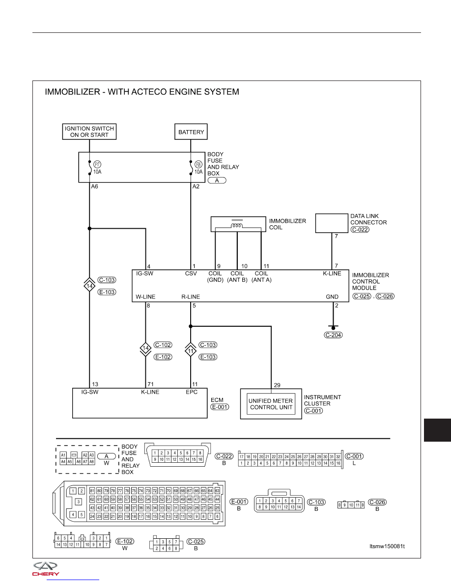
LTSMW150081T
15
|
|
|
Diagnostic Trouble Code (DTC) Tests B1000 - ECU Defect: Internal Errors DIAGNOSIS & TESTING LTSMW150081T 15
|