Chery Tiggo. Manual - part 389


  Index      Chery     Chery Tiggo - service repair manual 2009 year


Search            


Content   ..  387  388  389  390   ..


Chery Tiggo. Manual - part 389


NOTE :
The Restraints Control Module (RCM) ground pin must be connected to the vehicle chassis in the immediate location
of the RCM mounting area.

WARNING!

After installing the Restraints Control Module (RCM), make sure all of the connectors are firmly connected, and
the harness is routed properly. The resistance between the RCM housing and the vehicle body should be less
than 100 m

.

On Board Diagnostic Logic
• Self-diagnosis detection logic.
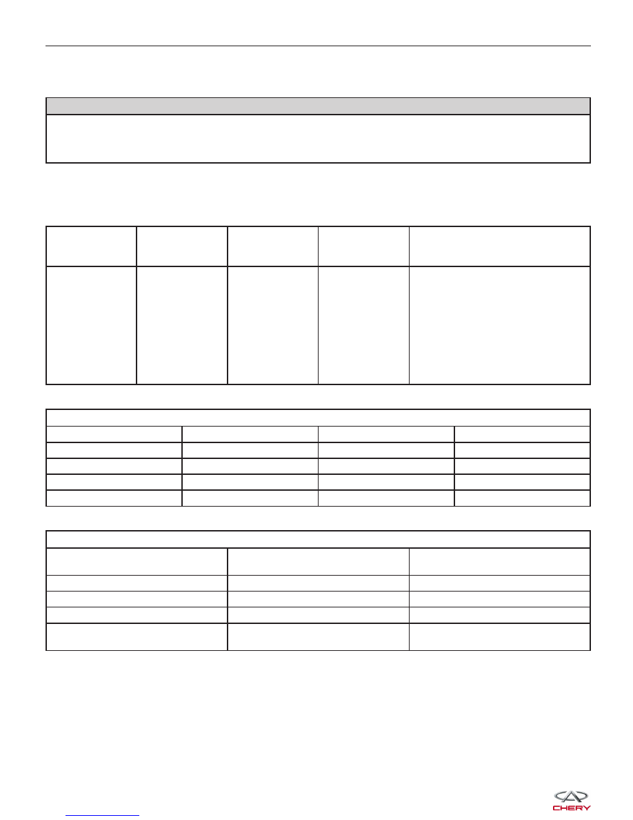
DTC NO.

DTC

DEFINITION

DTC

DETECTION

CONDITION

DTC SET

CONDITION

POSSIBLE CAUSE

B1352

Passenger

Airbag

Resistance Too

High Or Open

(1st Stage)

Ignition switch:

ON

Restraints
Control Module
(RCM) detected
that the
resistance of
RCM connector
terminals is out
of the
specification
range.

• Passenger airbag module

• Spiral cable

• Passenger airbag module
connector

• Harness is open between
passenger airbag module and RCM

• RCM

FIRING LOOP RESISTANCE FOR PASSENGER FRONT AIRBAG

COMPONENT

MIN.

NOMINAL

MAX.

Squib (Rs)

1.7

2.0

2.3

Wiring Harness (Rw)

0

0

0.2

Connector Terminals (Rt)

0

0

0.05

Total Resistance

1.7

2.0

2.55

TEST FOR PASSENGER FRONT AIRBAG FIRING LOOP DIAGNOSIS

RESISTANCE RANGE: R(DAB) =

Rs + Rt + Rw

DESCRIPTION

FAULT INDICATION

R(DAB) < 0.4

Resistance too low or short to GND

Fault definitely detected

1.60

⍀ ≤ R(DAB) < 4.84 ⍀

Normal

No fault

7.28

⍀ ≤ R(DAB)

Resistance too high

Fault definitely detected

0.4

⍀ < R(DAB) < 1.60 ⍀

4.84

⍀ < R(DAB) < 7.28 ⍀

Tolerance

Fault may or may not be detected

DIAGNOSIS & TESTING


FIRING LOOP FOR PASSENGER FRONT AIRBAG

DESCRIPTION

1: Rw - Wiring harness resistance

2: Rc - Contact coil resistance

3: Rs + Rt - Squib resistance + terminal resistance

4: Squib for passenger - side front airbag inflator

5: Contact coil

6: Wiring harness

7: HAE 3.5

R(DAB) = Rs + Rt + Rw

DTC Confirmation Procedure:

Before performing the following procedure, confirm that battery voltage is more than 12 V.

• Turn ignition switch off.

• Connect the X-431 scan tool to the Data Link Connector (DLC) - use the latest software available.

• Turn ignition switch on.

• With the scan tool, record and erase stored DTCs in the RCM.

• Turn ignition switch off and wait for a few seconds.

• Turn ignition switch on then select view DTC.

• If the DTC is detected, the DTC condition is current. Go to Diagnostic Procedure - Step 1.

• If the DTC is not detected, the DTC condition is intermittent (See Diagnostic Help and Intermittent DTC Trou-

bleshooting in Section 14 Restraints for more information).

Diagnostic Guide Lines

Observe the following guide lines while diagnosing this DTC:

• Troubleshoot any Engine Control Module (ECM) charging/cranking DTCs before proceeding.

• If the warning lamp goes out immediately after the warning lamp flashed for 6 - 7 seconds, this indicates that

the system is OK.

• If the warning lamp is on for 6 - 7 seconds continuously, then goes out, or the warning lamp is on continuously,

this indicates that there are history DTCs in the system. Use the Scan Tool to erase the DTCs.

• If any other condition occurs, use the Scan Tool to erase the history DTCs first, then check the warning lamp.

If the warning lamp does not go out immediately after the warning lamp flashes for 6 - 7 seconds when using
the Scan Tool, erase the history DTCs first.

• In the course of troubleshooting the airbag system, make sure the system power supply is shut off, and wait

two minutes for the system capacitor to discharge.

• The squib circuit connectors integrate a ⬙shorting⬙ spring (which prevents the airbag from deploying unintention-

ally due to static electricity by shorting the positive wire to the negative wire in the squib circuit when the con-
nectors are disconnected). Therefore, if the airbag electrical connector or spiral cable electrical connector is
damaged or improperly connected, the shorting spring may not be released when the electrical connector is
connected.

• The following tools are required to perform the DTC diagnostic procedure:

− X-431 Scan Tool
− Airbag Special Load Tool
− Digital Multimeter

NOTE :
While performing electrical diagnosis & testing, always refer to the electrical schematics for specific circuit
and component information.

DIAGNOSIS & TESTING

14


Diagnostic Procedure

1.

CHECK RCM DTC

• With the scan tool X-431, view DTCs in the RCM.

Is DTC B1352 present?

Yes

>>

Go to the next step.

No

>>

Go to step 6.

2.

CHECK FRONT PASSENGER AIRBAG MODULE

• Turn ignition switch off.

• Disconnect the negative battery cable.

WARNING!

To avoid serious or fatal injury, turn ignition switch off, disconnect the negative battery cable and wait two min-
utes before proceeding.

• Disconnect the passenger airbag module electrical connector.

NOTE :
Check connectors - Clean and repair as necessary.
• Connect the airbag special load tool to the spiral cable side of the vehicle harness (connect the special tool

resistor (2

⍀) in place of the passenger airbag module).

• Connect the negative battery cable.

WARNING!

To avoid serious or fatal injury, the passenger airbag module should not be check by multimeter.

NOTE :
If the airbag special load tool is not available, connect a known good passenger airbag module.

WARNING!

To avoid serious or fatal injury, reconnect the battery, then turn ignition switch on.

• Turn ignition switch on.

• With the scan tool, erase the DTC memory.

• Turn ignition switch off, and wait a few seconds, then turn ignition switch on.

• With the scan tool, read the RCM DTCs

Is DTC B1352 present?

Yes

>>

Go to the next step.

No

>>

Replace the passenger airbag module (See Passenger Airbag Module Removal & Installation in Sec-
tion 14 Restraints).
Reassemble the vehicle and road test to verify the customers complaint is repaired.

3.

CHECK PASSENGER AIRBAG MODULE CONTROL CIRCUITS

WARNING!

To avoid serious or fatal injury, turn ignition switch off, disconnect the negative battery cable and wait two min-
utes before proceeding.

DIAGNOSIS & TESTING


• Disconnect the airbag special load tool.
• Disconnect the RCM connector (1) (See Restraints

Control Module (RCM) Removal & Installation in
Section 14 Restraints).

NOTE :
Check connectors - Clean and repair as necessary.
• Check the harness for continuity of the passenger

airbag circuit between terminal 13 in the RCM elec-
trical connector J-001 terminal side and terminal 1
in the passenger airbag electrical connector J-002
terminal side.

• Continuity should exist.

CHECK CONTINUITY

FRONT

PASSENGER

AIRBAG

TERMINAL

RCM

TERMINAL

CONTINUITY

1

13

Yes

• Check the harness for continuity of the passenger airbag circuit between terminal 14 in the RCM electrical con-

nector J-001 terminal side and terminal 2 in the passenger airbag electrical connector J-002 terminal side.

• Continuity should exist.

CHECK CONTINUITY

FRONT

PASSENGER

AIRBAG

TERMINAL

RCM

TERMINAL

CONTINUITY

2

14

Yes

Is the check result normal?

Yes

>>

Go to the next step.

No

>>

Replace the spiral cable.

DIAGNOSIS & TESTING

LTSM140006

14


Content   ..  387  388  389  390   ..