Chery Tiggo. Manual - part 365


  Index      Chery     Chery Tiggo - service repair manual 2009 year


Search            


Content   ..  363  364  365  366   ..


Chery Tiggo. Manual - part 365


2.

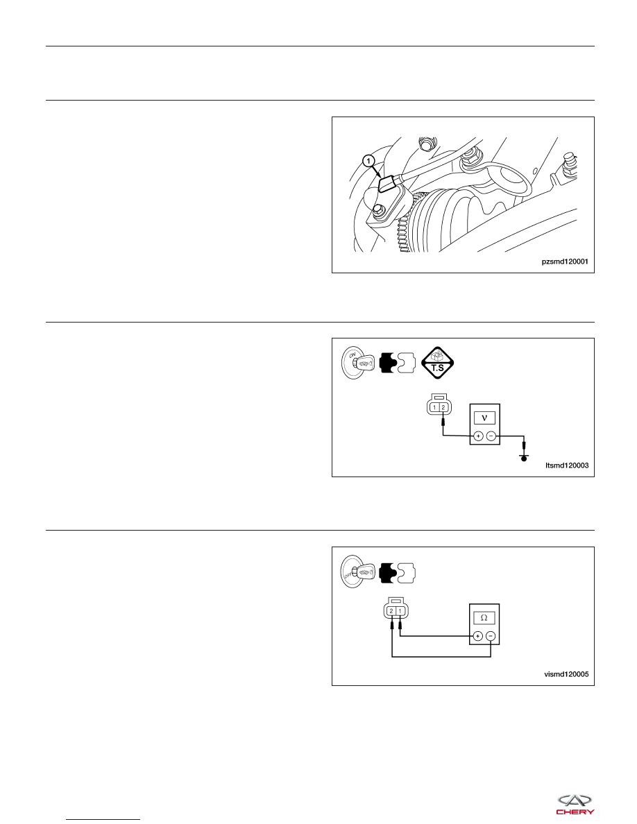
CHECK RIGHT FRONT WHEEL SPEED SENSOR ELECTRICAL CONNECTOR

• Turn ignition switch off.

• Disconnect the wheel speed sensor (1) electrical

connector.

• Inspect the wheel speed sensor electrical connector

for damage.

Is the electrical connector OK?

Yes

>>

Go to the next step.

No

>>

Repair or replace the electrical connector

as necessary.

3.

CHECK RIGHT FRONT WHEEL SPEED SENSOR REFERENCE SIGNAL CIRCUIT

• Turn ignition switch on.

• Measure the sensor reference voltage between ter-

minal 2 of the wheel speed sensor connector, ter-
minal side and ground.

• Voltage should exist (2.0 - 4.0 V).

Is the proper voltage present?

Yes

>>

Go to the next step.

No

>>

Repair or replace the circuit for an open,

short to ground or short to battery in connector or
harness.

4.

CHECK RIGHT FRONT WHEEL SPEED SENSOR RESISTANCE

• Check the wheel speed sensor resistance between

the sensor terminals 1 and 2, component side.

Is the sensor resistance 700 - 1500 ohms?

Yes

>>

Go to the next step.

No

>>

Replace the Right Front wheel speed

sensor.

DIAGNOSIS & TESTING

PZSMD120001

LTSMD120003

VISMD120005


5.

CHECK RIGHT FRONT WHEEL SPEED SENSOR GROUND CIRCUIT FOR AN OPEN

• Turn ignition switch off.

• Disconnect the ABS module electrical connector.

• For 1.6L/1.8L engine: Check the continuity between

terminal 20 of the ABS module connector E-002,
and terminal 1 of the Right Front wheel speed sen-
sor connector E-029, terminal side.

• For 2.0L/2.4L engine: Check the continuity between

terminal 20 of the ABS module connector A-020,
and terminal 1 of the Right Front wheel speed sen-
sor connector A-022, terminal side.

• Continuity should exist.

Is the check result normal?

Yes

>>

Go to the next step.

No

>>

Repair or replace the circuit for an open.

6.

CHECK RIGHT FRONT WHEEL SPEED SENSOR GROUND CIRCUIT FOR A SHORT TO GROUND

• Check the continuity between terminal 1 of the Right Front wheel speed sensor connector, terminal side and

ground.

• Continuity should not exist.

Is the check result normal?

Yes

>>

Go to the next step.

No

>>

Repair or replace the circuit for a short to ground.

7.

CHECK RIGHT FRONT WHEEL SPEED SENSOR GROUND CIRCUIT FOR A SHORT TO VOLTAGE

• Check the voltage between terminal 1 of the Right Front wheel speed sensor connector, terminal side and

ground.

• Voltage should not exist.

Is the check result normal?

Yes

>>

Go to the next step.

No

>>

Repair or replace the circuit for a short to battery.

8.

CHECK DTC

• With the X-431 scan tool, read the ABS module DTCs.

• Refer to ⬙DTC Confirmation Procedure⬙.

Is DTC C1203 present?

Yes

>>

Replace the ABS module (See ABS Module Removal & Installation in Section 12 Brakes).

No

>>

The system is now operating properly.
Erase all codes and test drive the vehicle to verify the repair is complete.

DIAGNOSIS & TESTING

LTSMD120006

12


C1206 - Left Rear Wheel Speed Sensor Circuit Open or Shorted

DIAGNOSIS & TESTING

LTSMW120014T


DIAGNOSIS & TESTING

LTSMW120006T

12


Content   ..  363  364  365  366   ..